
ESP32-Controlled Robotic Platform with Sensor Integration and Wireless Communication
View and Edit Project In Cirkit Designer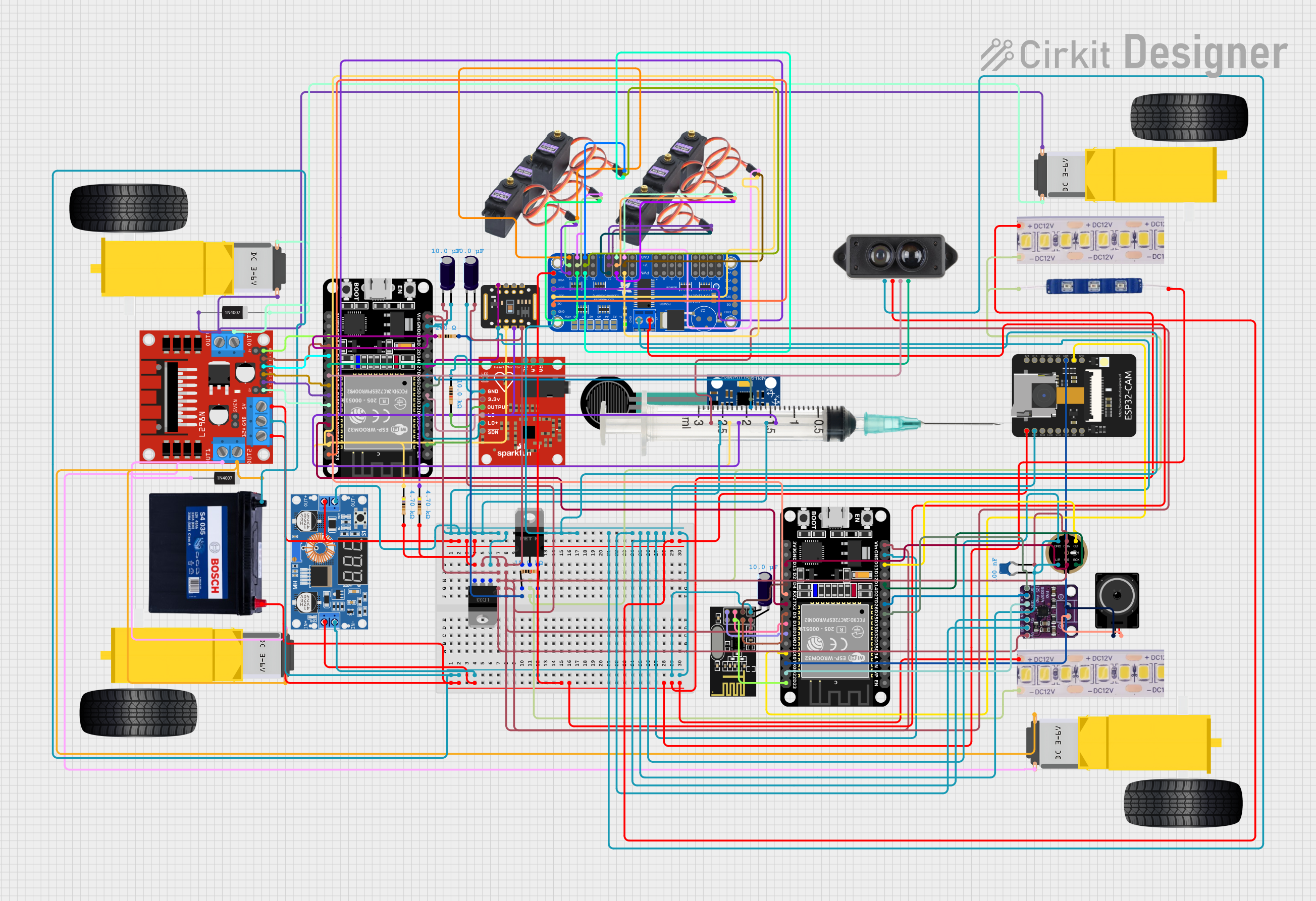
Circuit Documentation
Summary
This circuit is designed to control a variety of components including DC gearmotors, LEDs, sensors, and communication modules, all managed by an ESP32 microcontroller. The circuit features motor driving capabilities through an L298N DC motor driver, power regulation using an XL4015 step-down module and an LD33 voltage regulator, and various sensors and communication modules for data acquisition and wireless communication. The circuit is powered by a 12V 200Ah battery and includes protection and filtering components such as diodes and capacitors.
Component List
Microcontrollers
- ESP32 (30 pin): A microcontroller with Wi-Fi and Bluetooth capabilities, featuring a wide range of GPIO pins for interfacing with various sensors and peripherals.
Power Supply and Regulation
- 12V 200Ah Battery: Provides the main power source for the circuit.
- XL4015 5A DC Buck Step-down: A voltage step-down module that regulates the input voltage to a lower level.
- LD33 Low-Dropout Voltage Regulator: Provides a stable 3.3V output from a higher voltage input.
Motor Driver and Motors
- L298N DC motor driver: Controls the direction and speed of DC gearmotors.
- Gearmotor DC Wheels (left and right): Act as the driving mechanism for a vehicle or robotic platform.
Sensors
- MAX30102: An integrated pulse oximetry and heart-rate monitor sensor module.
- MPU-6050: A 6-axis gyroscope and accelerometer module for motion tracking.
- AD8232 HeartRate Monitor: A single-lead heart rate monitor.
- LiDAR TF Mini S: A distance measurement sensor.
- Force Sensing Resistor: A sensor that changes its resistance with applied force.
- INMP441 FRONT MIC: A high-performance digital I2S output microphone.
Communication Modules
- NRF24L01: A wireless communication module for short-range communication.
- ESP32 - CAM: A camera module with Wi-Fi capabilities.
Actuators
- MG996R: High-torque digital servos for actuation purposes.
- Adafruit 16-Channel 12-bit PWM Servo Driver - I2C: A PWM driver capable of controlling multiple servos.
Indicators
- 12V White LED strip: Used for illumination or indication.
- 12v Blue LED: An indicator LED.
Protection and Filtering
- 1N4007 Rectifier Diode: Used for protecting the circuit from reverse voltage.
- Electrolytic Capacitor: Used for filtering and stabilizing the power supply.
- Ceramic Capacitor: Provides noise filtering in the circuit.
- Resistor: Various resistors used for current limiting and voltage division.
Audio Components
- Max98357: An I2S Class D amplifier module.
- Loudspeaker: An audio output device.
Wiring Details
Power Supply and Regulation
- 12V 200Ah Battery supplies power to the L298N DC motor driver, XL4015 5A DC Buck Step-down, and Adafruit 16-Channel 12-bit PWM Servo Driver - I2C.
- XL4015 5A DC Buck Step-down regulates the voltage for the LD33 Low-Dropout Voltage Regulator.
- LD33 Low-Dropout Voltage Regulator provides 3.3V to various components including the ESP32, INMP441 FRONT MIC, NRF24L01, Max98357, and AD8232 HeartRate Monitor.
Motor Driver and Motors
- L298N DC motor driver controls the Gearmotor DC Wheels (left and right) with inputs from the ESP32 and protection from 1N4007 Rectifier Diodes.
Sensors
- MAX30102, MPU-6050, AD8232 HeartRate Monitor, LiDAR TF Mini S, and Force Sensing Resistor are connected to the ESP32 for data acquisition.
Communication Modules
- NRF24L01 is interfaced with the ESP32 for wireless communication.
- ESP32 - CAM is connected to another ESP32 for camera control and data transfer.
Actuators
- MG996R servos are controlled by the Adafruit 16-Channel 12-bit PWM Servo Driver - I2C, which is in turn controlled by the ESP32.
Indicators
- 12V White LED strip and 12v Blue LED are powered by the 12V 200Ah Battery with current limiting provided by resistors.
Audio Components
- Max98357 is connected to the ESP32 for audio signal processing and drives the Loudspeaker.
Documented Code
ESP32 Microcontroller Code (sketch.ino)
void setup() {
  // put your setup code here, to run once:

}

void loop() {
  // put your main code here, to run repeatedly:

}
Note: The actual functionality of the code will depend on the specific requirements of the circuit and the tasks it needs to perform. The provided code template is a starting point for further development.