
ATmega328P Microcontroller-Driven Stepper Motor with DRV8825
View and Edit Project In Cirkit Designer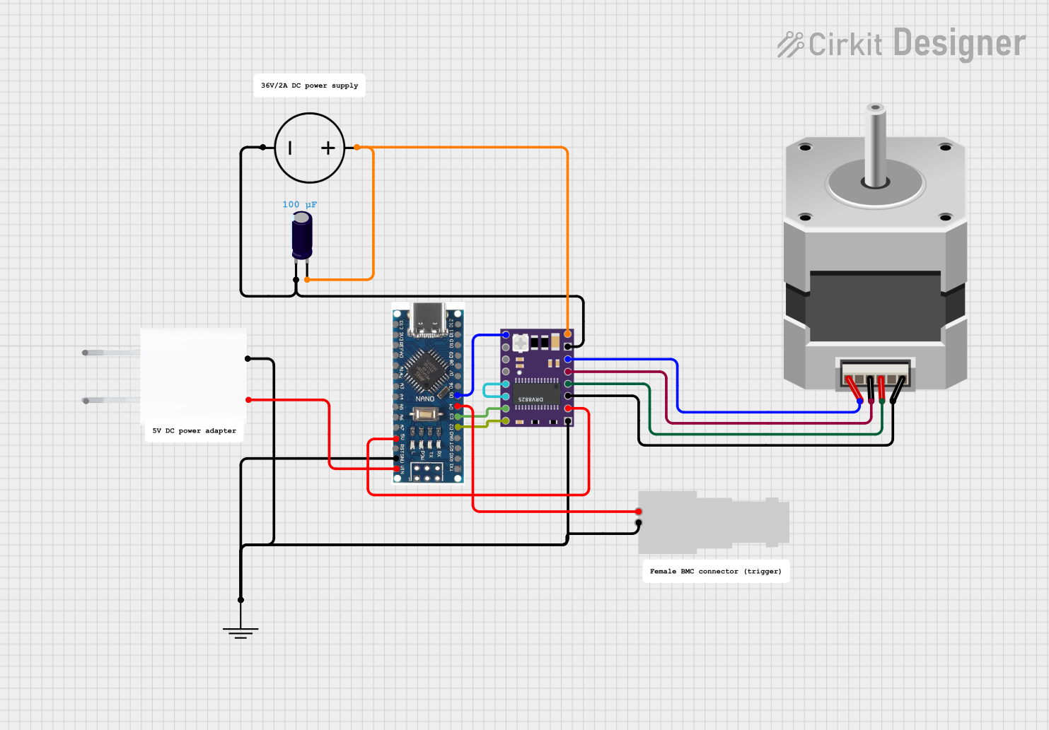
Circuit Documentation
Summary
This circuit is designed to control a bipolar stepper motor using a Nano 3.0 ATmega328P microcontroller board and a DRV 8825 stepper motor driver. The circuit is powered by a 5V adapter and includes an electrolytic capacitor for voltage smoothing. A female BNC connector is used for external interfacing. Ground connections are established through a common ground net, and a DC power source is used to provide motor voltage to the DRV 8825.
Component List
Nano 3.0 ATmega328P Type-C USB CH340 Controller Board
- Microcontroller board based on the ATmega328P
- Features digital I/O pins, analog inputs, and various power pins
- Used as the main controller for the stepper motor driver
DRV 8825
- Stepper motor driver capable of driving a bipolar stepper motor
- Provides features like adjustable current limiting and microstepping
- Controlled by the Nano 3.0 board
Stepper Motor (Bipolar)
- A bipolar stepper motor with four wires
- Driven by the DRV 8825 to perform precise movements
Electrolytic Capacitor
- Capacitance: 0.0001 Farads
- Used for voltage smoothing on the motor power supply
GND
- Represents the common ground connection in the circuit
DC Power Source
- Provides the motor voltage for the DRV 8825 and the stepper motor
Female BNC
- Connector used for external interfacing with the circuit
5V Adapter
- Provides a regulated 5V output for powering the Nano 3.0 board
Wiring Details
Nano 3.0 ATmega328P Type-C USB CH340 Controller Board
5Vconnected to DRV 8825FAULTpinGNDconnected to common ground netVINconnected to 5V Adapter5VoutputD5connected to DRV 8825ENpinD4connected to Female BNCPin 1D3connected to DRV 8825STEPpinD2connected to DRV 8825DIRpin
DRV 8825
FAULTconnected to Nano 3.05VpinGND LOGICconnected to common ground netENconnected to Nano 3.0D5pinSTEPconnected to Nano 3.0D3pinDIRconnected to Nano 3.0D2pinRSTconnected toSLP(self-loop)VMOTconnected to DC Power SourcePositiveand Electrolytic Capacitor+GND MOTORconnected to DC Power SourceGroundand Electrolytic Capacitor-B2connected to Stepper MotorAB1connected to Stepper MotorCA1connected to Stepper MotorBA2connected to Stepper MotorD
Stepper Motor (Bipolar)
Aconnected to DRV 8825B2pinBconnected to DRV 8825A1pinCconnected to DRV 8825B1pinDconnected to DRV 8825A2pin
Electrolytic Capacitor
+connected to DC Power SourcePositiveand DRV 8825VMOTpin-connected to DC Power SourceGroundand DRV 8825GND MOTORpin
GND
GNDconnected to common ground net
DC Power Source
Positiveconnected to DRV 8825VMOTand Electrolytic Capacitor+Groundconnected to DRV 8825GND MOTORand Electrolytic Capacitor-
Female BNC
Pin 1connected to Nano 3.0D4pinPin 2connected to common ground net
5V Adapter
GNDconnected to common ground net5Vconnected to Nano 3.0VINpin
Documented Code
No code was provided for the microcontroller. The documentation for the code would typically include a description of the functionality, setup, and main loop, along with comments explaining the purpose of each section of the code. Since no code is available, this section cannot be completed. If code becomes available, it should be documented here following the standard practices for code documentation, including descriptions of the functions, variables, and logic used to control the stepper motor and interface with other components.