
Circuit Documentation
Summary
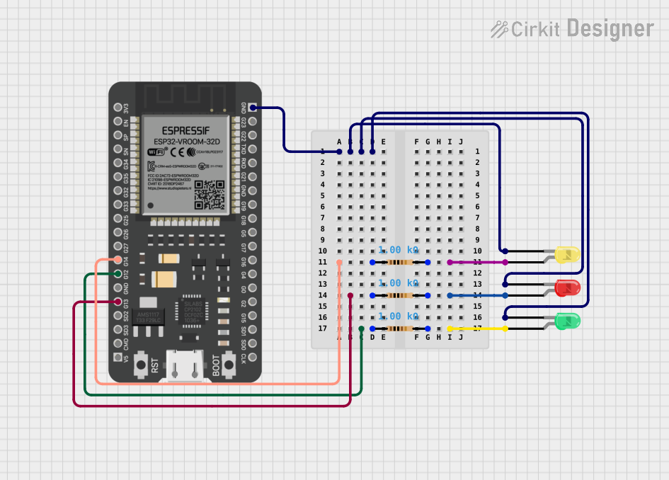
This circuit is designed around the ESP32 microcontroller, which is a versatile and powerful microcontroller with a wide range of GPIO pins. The circuit includes three LEDs (red, green, and yellow) each with a corresponding resistor to limit the current through the LEDs. The ESP32 controls the LEDs, which are likely used as indicators for various statuses or events in the application. The resistors are all 1k Ohm, providing a balance between brightness and power consumption for the LEDs.
Component List
ESP32 - 38 pins
- Description: A microcontroller with Wi-Fi and Bluetooth capabilities and a wide range of GPIO pins.
- Purpose: Acts as the central processing unit of the circuit, controlling the LEDs and handling communication and data processing.
LED: Two Pin (green)
- Description: A standard green LED for indication purposes.
- Purpose: Serves as a visual indicator, likely representing a specific status or condition when lit.
LED: Two Pin (yellow)
- Description: A standard yellow LED for indication purposes.
- Purpose: Serves as a visual indicator, likely representing a different status or condition when lit compared to the green LED.
LED: Two Pin (red)
- Description: A standard red LED for indication purposes.
- Purpose: Serves as a visual indicator, likely representing a warning or error condition when lit.
Resistor (1k Ohm)
- Description: A resistor with a resistance of 1000 Ohms.
- Purpose: Limits the current through the LEDs to prevent damage and control brightness.
Wiring Details
ESP32 - 38 pins
- GND: Connected to the cathodes of the red, green, and yellow LEDs.
- G14: Connected to a 1k Ohm resistor leading to the anode of the yellow LED.
- G13: Connected to a 1k Ohm resistor leading to the anode of the red LED.
- G12: Connected to a 1k Ohm resistor leading to the anode of the green LED.
LED: Two Pin (green)
- Cathode: Connected to GND on the ESP32.
- Anode: Connected to a 1k Ohm resistor, which is connected to pin G12 on the ESP32.
LED: Two Pin (yellow)
- Cathode: Connected to GND on the ESP32.
- Anode: Connected to a 1k Ohm resistor, which is connected to pin G14 on the ESP32.
LED: Two Pin (red)
- Cathode: Connected to GND on the ESP32.
- Anode: Connected to a 1k Ohm resistor, which is connected to pin G13 on the ESP32.
Resistor (1k Ohm)
- Pin1: Connected to the corresponding GPIO pin on the ESP32 (G12, G13, or G14).
- Pin2: Connected to the anode of the corresponding LED (green, red, or yellow).
Documented Code
No code has been provided for the microcontroller. The ESP32 is expected to be programmed to control the LEDs based on the application's requirements. The code would typically initialize the GPIO pins as outputs and then turn the LEDs on or off by setting the pins high or low, respectively.