
Arduino UNO Based Ultrasonic Distance Measurement with LCD Display
View and Edit Project In Cirkit Designer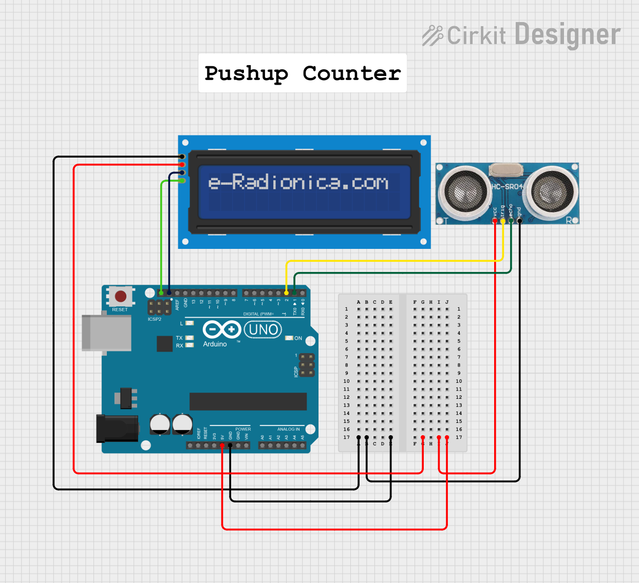
Circuit Documentation
Summary
This circuit integrates an Arduino UNO microcontroller with an Ultrasonic Sensor and an LCD screen (16x2 with I2C interface). The purpose of the circuit is to measure distances using the Ultrasonic Sensor and display the results on the LCD screen. The Arduino UNO serves as the central processing unit, controlling the sensor and managing the data display on the LCD.
Component List
Ultrasonic Sensor
- Pins: +VCC, Trigger, Echo, GND
- Description: A sensor that measures distance by emitting ultrasonic waves and detecting the reflection.
- Purpose: To measure the distance to an object and provide this information to the Arduino UNO.
LCD screen 16x2 I2C
- Pins: SCL, SDA, VCC, GND
- Description: A 16x2 character LCD display with an I2C interface for displaying text.
- Purpose: To display the distance measurements received from the Arduino UNO.
Arduino UNO
- Pins: UNUSED, IOREF, Reset, 3.3V, 5V, GND, Vin, A0-A5, SCL, SDA, AREF, D0-D13
- Description: A microcontroller board based on the ATmega328P, with digital and analog I/O pins.
- Purpose: To control the Ultrasonic Sensor and LCD screen, process the distance measurements, and display the results.
Comment
- Pins: None
- Description: Not applicable.
- Purpose: Not applicable.
Wiring Details
Ultrasonic Sensor
- +VCC: Connected to the 5V output from the Arduino UNO.
- Trigger: Connected to digital pin D2 on the Arduino UNO.
- Echo: Connected to digital pin D1 on the Arduino UNO.
- GND: Connected to the ground (GND) on the Arduino UNO.
LCD screen 16x2 I2C
- SCL: Connected to the SCL pin on the Arduino UNO.
- SDA: Connected to the SDA pin on the Arduino UNO.
- VCC: Connected to the 5V output from the Arduino UNO.
- GND: Connected to the ground (GND) on the Arduino UNO.
Arduino UNO
- 5V: Provides power to the Ultrasonic Sensor and LCD screen.
- GND: Common ground for the Ultrasonic Sensor and LCD screen.
- SCL: I2C clock line connected to the LCD screen.
- SDA: I2C data line connected to the LCD screen.
- D2: Digital output to the Trigger pin of the Ultrasonic Sensor.
- D1: Digital input from the Echo pin of the Ultrasonic Sensor.
Documented Code
void setup() {
  // put your setup code here, to run once:

}

void loop() {
  // put your main code here, to run repeatedly:

}
File: sketch.ino
The provided code is a template with empty setup() and loop() functions, which are the standard structure for Arduino sketches. The setup() function is intended to contain initialization code that runs once when the microcontroller is powered on or reset. The loop() function is designed to contain the main logic of the program, which runs repeatedly as long as the microcontroller is powered.
Further implementation is required to initialize the I2C interface for the LCD screen, configure the pins for the Ultrasonic Sensor, and write the logic for measuring distances and displaying the results on the LCD screen.