
ESP32-Based Wi-Fi Controlled Smart Lighting System with Nextion Touch LCD
View and Edit Project In Cirkit Designer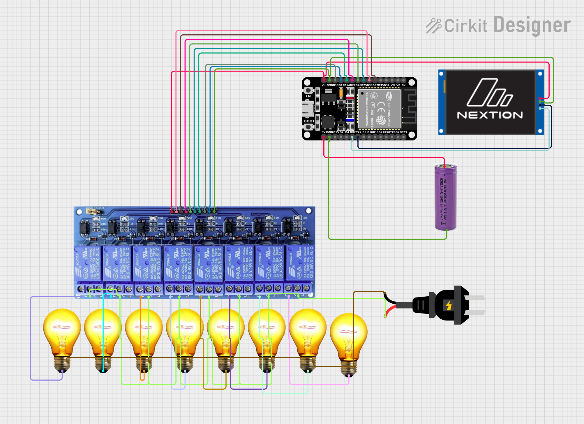
Circuit Documentation
Summary
This circuit is designed to control multiple AC bulbs using an ESP32 microcontroller and an 8-channel relay module. The system also includes a Nextion Touch LCD for user interaction. The ESP32 is powered by a 3.3V battery, and the AC bulbs are powered by an AC source.
Component List
ESP32 (30 pin)
- Description: A powerful microcontroller with built-in Wi-Fi and Bluetooth capabilities.
- Pins: EN, VP, VN, D34, D35, D32, D33, D25, D26, D27, D14, D12, D13, GND, Vin, D23, D22, TX0, RX0, D21, D19, D18, D5, TX2, RX2, D4, D2, D15, 3V3
8 Channel Relay JD-VCC
- Description: A relay module that allows control of high voltage devices.
- Pins: JD-VCC, VCC, GND, In8, In7, In6, In5, In4, In3, In2, In1, In1_NC, IN1_COM, IN1_NO, IN2_NC, IN2_COM, IN2_NO, IN3_NC, IN3_COM, IN3_NO, IN4_NC, IN4_COM, IN4_NO, IN5_NC, IN5_COM, IN5_NO, IN6_NC, IN6_COM, IN6_NO, IN7_NC, IN7_COM, IN7_NO, IN8_NC, IN8_COM, IN8_NO
3.3V Battery
- Description: A battery providing 3.3V power supply.
- Pins: +, -
AC Bulb
- Description: Standard AC bulbs used for lighting.
- Pins: P, N
Nextion Touch LCD 2.4"
- Description: A touch-sensitive LCD display for user interaction.
- Pins: VCC, GND, RX, TX
AC Source
- Description: Provides AC power to the bulbs.
- Pins: +, -
Wiring Details
ESP32 (30 pin)
- D32: Connected to In7 of the 8 Channel Relay JD-VCC
- D33: Connected to In8 of the 8 Channel Relay JD-VCC
- D25: Connected to In4 of the 8 Channel Relay JD-VCC
- D26: Connected to In5 of the 8 Channel Relay JD-VCC
- D27: Connected to In6 of the 8 Channel Relay JD-VCC
- D14: Connected to In3 of the 8 Channel Relay JD-VCC
- D12: Connected to In1 of the 8 Channel Relay JD-VCC
- D13: Connected to In2 of the 8 Channel Relay JD-VCC
- GND: Connected to GND of the Nextion Touch LCD 2.4" and GND of the 8 Channel Relay JD-VCC
- Vin: Connected to VCC of the Nextion Touch LCD 2.4" and VCC of the 8 Channel Relay JD-VCC
- TX2: Connected to TX of the Nextion Touch LCD 2.4"
- RX2: Connected to RX of the Nextion Touch LCD 2.4"
- GND: Connected to - of the 3.3V Battery
- 3V3: Connected to + of the 3.3V Battery
8 Channel Relay JD-VCC
- In7: Connected to D32 of the ESP32
- In8: Connected to D33 of the ESP32
- In4: Connected to D25 of the ESP32
- In5: Connected to D26 of the ESP32
- In6: Connected to D27 of the ESP32
- In3: Connected to D14 of the ESP32
- In1: Connected to D12 of the ESP32
- In2: Connected to D13 of the ESP32
- GND: Connected to GND of the ESP32
- VCC: Connected to Vin of the ESP32
- IN1_COM, IN2_COM, IN3_COM, IN4_COM, IN5_COM, IN6_COM, IN7_COM, IN8_COM: Connected to + of the AC Source
- IN1_NO: Connected to P of the AC Bulb
- IN2_NO: Connected to P of the AC Bulb
- IN3_NO: Connected to P of the AC Bulb
- IN4_NO: Connected to P of the AC Bulb
- IN5_NO: Connected to P of the AC Bulb
- IN6_NO: Connected to P of the AC Bulb
- IN7_NO: Connected to P of the AC Bulb
- IN8_NO: Connected to P of the AC Bulb
3.3V Battery
- -: Connected to GND of the ESP32
- +: Connected to 3V3 of the ESP32
AC Bulb
- P: Connected to IN1_NO of the 8 Channel Relay JD-VCC
- P: Connected to IN2_NO of the 8 Channel Relay JD-VCC
- P: Connected to IN3_NO of the 8 Channel Relay JD-VCC
- P: Connected to IN4_NO of the 8 Channel Relay JD-VCC
- P: Connected to IN5_NO of the 8 Channel Relay JD-VCC
- P: Connected to IN6_NO of the 8 Channel Relay JD-VCC
- P: Connected to IN7_NO of the 8 Channel Relay JD-VCC
- P: Connected to IN8_NO of the 8 Channel Relay JD-VCC
- N: Connected to N of the AC Source
Nextion Touch LCD 2.4"
- GND: Connected to GND of the ESP32
- VCC: Connected to Vin of the ESP32
- RX: Connected to RX2 of the ESP32
- TX: Connected to TX2 of the ESP32
AC Source
- +: Connected to IN1_COM, IN2_COM, IN3_COM, IN4_COM, IN5_COM, IN6_COM, IN7_COM, IN8_COM of the 8 Channel Relay JD-VCC
- -: Connected to N of all AC Bulbs
Code Documentation
#include <INextionBooleanValued.h>
#include <INextionCallback.h>
#include <INextionColourable.h>
#include <INextionFontStyleable.h>
#include <INextionNumericalValued.h>
#include <INextionStringValued.h>
#include <INextionTouchable.h>
#include <INextionWidget.h>
#include <Nextion.h>
#include <NextionButton.h>
#include <NextionCallbackFunctionHandler.h>
#include <NextionCheckbox.h>
#include <NextionCrop.h>
#include <NextionDualStateButton.h>
#include <NextionGauge.h>
#include <NextionHotspot.h>
#include <NextionNumber.h>
#include <NextionPage.h>
#include <NextionPicture.h>
#include <NextionProgressBar.h>
#include <NextionRadioButton.h>
#include <NextionSlider.h>
#include <NextionSlidingText.h>
#include <NextionText.h>
#include <NextionTimer.h>
#include <NextionTypes.h>
#include <NextionVariableNumeric.h>
#include <NextionVariableString.h>
#include <NextionWaveform.h>
#include <esp32_azureiotkit_sensors.h>

// Relay Pins
#define RELAY1 12
#define RELAY2 13
#define RELAY3 14
#define RELAY4 25
#define RELAY5 26
#define RELAY6 27
#define RELAY7 32
#define RELAY8 33

// Relay State
bool relayState[8] = {false, false, false, false, false, false, false, false};

// Nextion Display Setup
#define RX_PIN 16
#define TX_PIN 17
Nextion myNextion(RX_PIN, TX_PIN);

// Function to Update Relays
void updateRelay(int relay, bool state) {
  digitalWrite(relay, state ? LOW : HIGH);  // Active LOW
}

// Function to Sync with Nextion Display
void updateNextion(int button