
Circuit Documentation
Summary of the Circuit
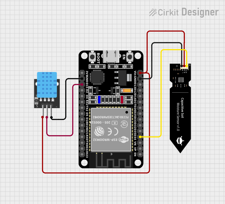
This circuit integrates an ESP32 microcontroller with a DHT11 temperature and humidity sensor and a DFRobot Capacitive Soil Moisture Sensor. The ESP32 serves as the central processing unit, reading data from the DHT11 and the soil moisture sensor. The DHT11 is powered by the ESP32 and communicates via a single data line. The soil moisture sensor is also powered by the ESP32 and outputs an analog signal that is read by one of the ESP32's analog input pins.
Component List
ESP32 (30 pin)
- Description: A powerful microcontroller with Wi-Fi and Bluetooth capabilities, featuring a wide range of GPIO pins for interfacing with various sensors and peripherals.
- Pins: EN, VP, VN, D34, D35, D32, D33, D25, D26, D27, D14, D12, D13, GND, Vin, D23, D22, TX0, RX0, D21, D19, D18, D5, TX2, RX2, D4, D2, D15, 3V3
DHT11
- Description: A basic, low-cost digital temperature and humidity sensor that provides a calibrated digital output.
- Pins: 5V, S, GND
DFRobot Capacitive Soil Moisture Sensor (V1.0)
- Description: A sensor that measures the moisture content in soil using capacitive sensing rather than resistive sensing, making it less prone to corrosion.
- Pins: A, VCC, GND
Wiring Details
ESP32 (30 pin)
- D34: Connected to the analog output (A) of the DFRobot Capacitive Soil Moisture Sensor.
- GND: Common ground with DHT11 and DFRobot Capacitive Soil Moisture Sensor.
- Vin: Powers the DHT11 and DFRobot Capacitive Soil Moisture Sensor.
- D15: Connected to the signal pin (S) of the DHT11.
DHT11
- 5V: Powered by the Vin of the ESP32.
- S: Signal pin connected to D15 of the ESP32.
- GND: Common ground with ESP32.
DFRobot Capacitive Soil Moisture Sensor (V1.0)
- A: Analog output connected to D34 of the ESP32.
- VCC: Powered by the Vin of the ESP32.
- GND: Common ground with ESP32.
Documented Code
Since no code was provided in the input, this section is currently empty. When code is available, it should be documented here with explanations of how the microcontroller interfaces with the sensors, including initialization, reading sensor values, and any communication protocols used (e.g., I2C, UART, SPI).
Please note that the actual implementation of the code will depend on the specific requirements of the application, such as the frequency of sensor readings, data processing, and communication needs.