Cirkit Designer
Your all-in-one circuit design IDE
Home /
Project Documentation
Arduino UNO Solar-Powered AI Vision Servo Controller
Circuit Documentation
Summary
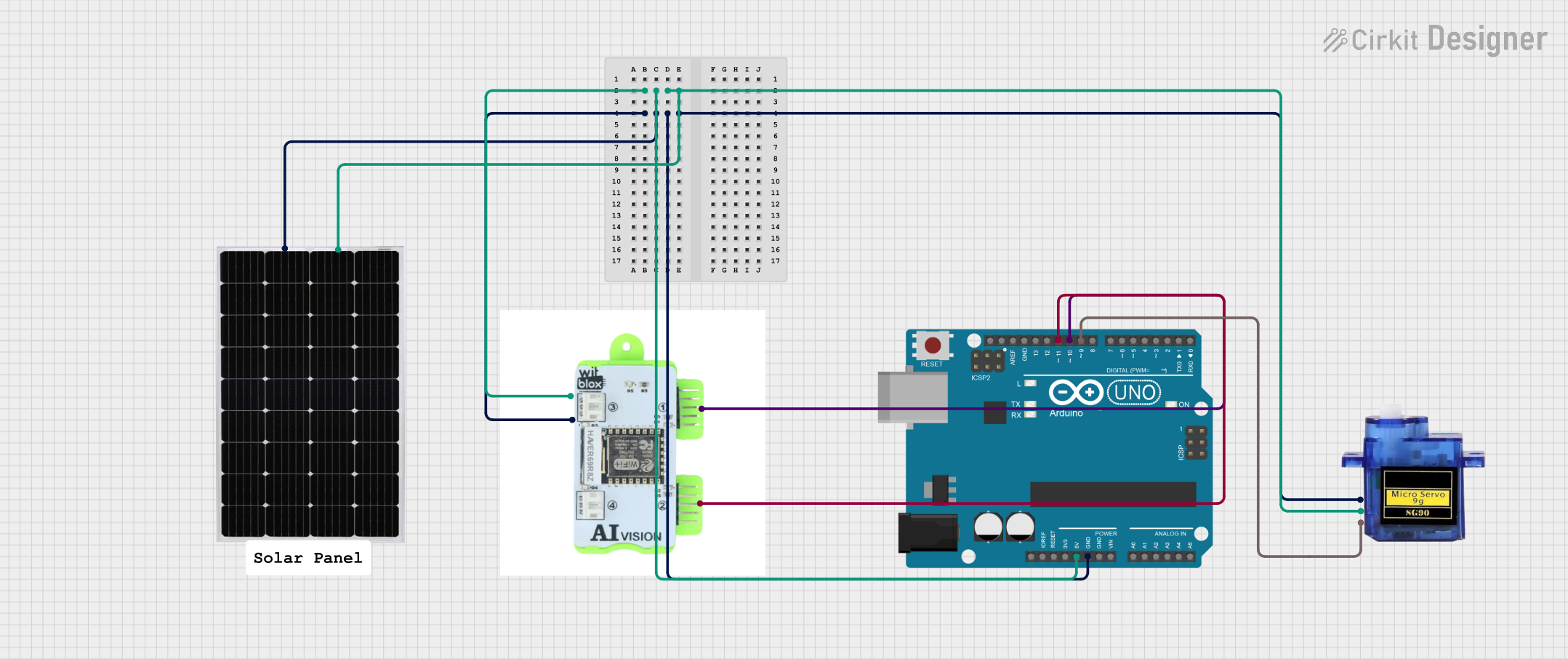
This circuit integrates an Arduino UNO microcontroller, an AI Vision Blox, a Micro servo 9G, and a Solar Panel. The Arduino UNO controls the Micro servo based on inputs from the AI Vision Blox. The entire system is powered by the Solar Panel.
Component List
Arduino UNO
- Description: A microcontroller board based on the ATmega328P.
- Pins: UNUSED, IOREF, Reset, 3.3V, 5V, GND, Vin, A0, A1, A2, A3, A4, A5, SCL, SDA, AREF, D13, D12, D11, D10, D9, D8, D7, D6, D5, D4, D3, D2, D1, D0
AI Vision Blox
- Description: A vision processing module with two output pins.
- Pins: Output 1, Output 2, Positive, Negative
Micro servo 9G
- Description: A small servo motor used for precise control of angular position.
- Pins: GND, +5V, PWM
Solar Panel
- Description: A solar panel used to power the circuit.
- Pins: +, -
Comment
- Description: A placeholder for comments in the circuit design.
- Pins: None
Wiring Details
Arduino UNO
- 5V: Connected to +5V of Micro servo 9G, Positive of AI Vision Blox, and + of Solar Panel.
- GND: Connected to GND of Micro servo 9G, Negative of AI Vision Blox, and - of Solar Panel.
- D11: Connected to Output 2 of AI Vision Blox.
- D10: Connected to Output 1 of AI Vision Blox.
- D9: Connected to PWM of Micro servo 9G.
AI Vision Blox
- Positive: Connected to 5V of Arduino UNO, +5V of Micro servo 9G, and + of Solar Panel.
- Negative: Connected to GND of Arduino UNO, GND of Micro servo 9G, and - of Solar Panel.
- Output 1: Connected to D10 of Arduino UNO.
- Output 2: Connected to D11 of Arduino UNO.
Micro servo 9G
- +5V: Connected to 5V of Arduino UNO, Positive of AI Vision Blox, and + of Solar Panel.
- GND: Connected to GND of Arduino UNO, Negative of AI Vision Blox, and - of Solar Panel.
- PWM: Connected to D9 of Arduino UNO.
Solar Panel
- +: Connected to 5V of Arduino UNO, +5V of Micro servo 9G, and Positive of AI Vision Blox.
- -: Connected to GND of Arduino UNO, GND of Micro servo 9G, and Negative of AI Vision Blox.
Code Documentation
Arduino UNO Code
#include <Servo.h>

Servo myServo;
const int input1 = 10;
const int input2 = 11;

void setup() {
  myServo.attach(9);
  myServo.write(90); // Initialize servo at 90 degrees
  pinMode(input1, INPUT);
  pinMode(input2, INPUT);
}

void loop() {
  int state1 = digitalRead(input1);
  int state2 = digitalRead(input2);

  if (state1 == HIGH && state2 == LOW) {
    myServo.write(180); // Move servo to 180 degrees
  } else if (state2 == HIGH && state1 == LOW) {
    myServo.write(0); // Move servo to 0 degrees
  } else {
    myServo.write(90); // Return to default position if no inputs are HIGH
  }

  delay(1000); // Delay to stabilize readings
}
This code initializes the servo motor to 90 degrees and reads the states of two input pins (D10 and D11). Depending on the states of these inputs, the servo motor is moved to 0, 90, or 180 degrees. The delay of 1000 milliseconds is used to stabilize the readings.