Cirkit Designer
Your all-in-one circuit design IDE
Home /
Project Documentation
Arduino Nano Based GPS Tracker with GSM Alert and Panic Button
Circuit Documentation
Summary
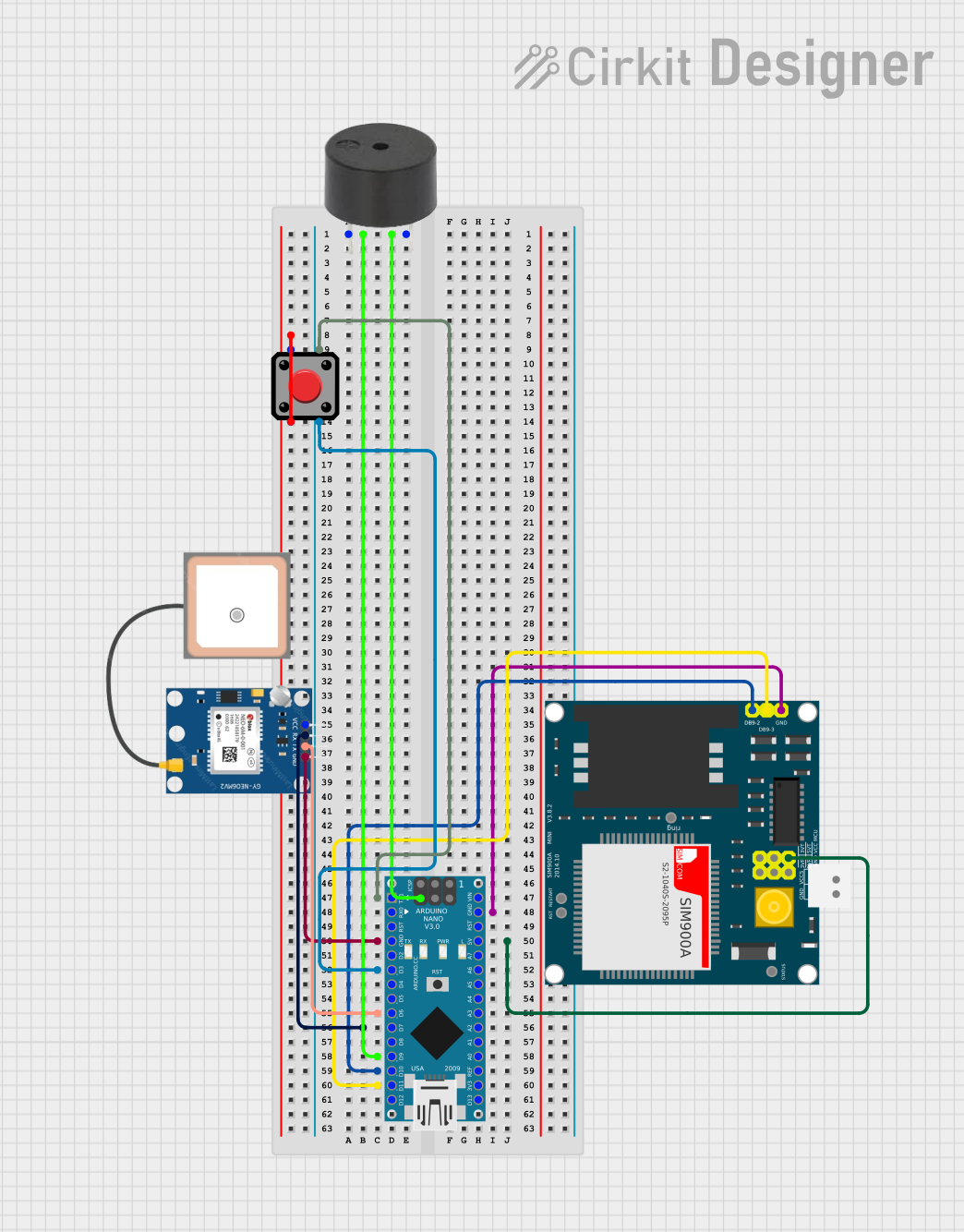
This circuit integrates an Arduino Nano with a GPS module (NEO 6M), a GSM module (SIM900A), a buzzer, and a pushbutton. The primary function of this circuit is to provide location tracking and emergency alert capabilities. When the pushbutton is pressed, the buzzer is activated, and the GPS coordinates are sent via SMS using the GSM module.
Component List
Arduino Nano
- Microcontroller board based on the ATmega328P
- It has a variety of digital and analog I/O pins
- Used as the central processing unit for controlling other components
GPS NEO 6M
- A GPS module capable of providing geolocation information
- Communicates with the Arduino Nano via serial connection
SIM900A
- A GSM/GPRS module for cellular communication
- Allows sending SMS and can be used for mobile communication
Buzzer
- An electromechanical component that produces sound
- Used to provide an audible alert when the pushbutton is pressed
Pushbutton
- A simple switch mechanism for controlling some aspect of a machine or a process
- Used to trigger the emergency alert system
Wiring Details
Arduino Nano
- D9 connected to the buzzer
- GND connected to the buzzer, GPS NEO 6M, and SIM900A for common ground
- 5V supplies power to the SIM900A
- D3 connected to the pushbutton
- D6 connected to the GPS NEO 6M TX pin
- D7 connected to the GPS NEO 6M RX pin
- D10 connected to the SIM900A TXD pin
- D11/MOSI connected to the SIM900A RXD pin
GPS NEO 6M
- VCC not connected (requires connection to a power source)
- RX connected to Arduino Nano D7
- TX connected to Arduino Nano D6
- GND connected to Arduino Nano GND
SIM900A
- GND connected to Arduino Nano GND
- DB9-3 (RXD) connected to Arduino Nano D11/MOSI
- DB9-2 (TXD) connected to Arduino Nano D10
- VCC connected to Arduino Nano 5V
Buzzer
- PIN connected to Arduino Nano D9
- GND connected to Arduino Nano GND
Pushbutton
- Pin 2 connected to Pin 1 (requires clarification on usage)
- Pin 3 connected to Arduino Nano D3
- Pin 4 connected to Arduino Nano D1/TX (requires clarification on usage)
Documented Code
#include <SoftwareSerial.h>
#include <TinyGPS++.h>

// Pin definitions
const int buttonPin = 2;     // Button connected to PIN 2
const int buzzerPin = 9;     // Buzzer connected to PIN 9
const int gsmTx = 10;        // GSM module TX pin connected to PIN 10
const int gsmRx = 11;        // GSM module RX pin connected to PIN 11
const int gpsRx = 6;         // GPS module TX pin connected to PIN 6 (SoftwareSerial)
const int gpsTx = 7;         // GPS module RX pin connected to PIN 7 (SoftwareSerial)

SoftwareSerial gsmSerial(gsmRx, gsmTx); // RX, TX for GSM
SoftwareSerial gpsSerial(gpsRx, gpsTx); // RX, TX for GPS
TinyGPSPlus gps; // GPS object

float cachedLatitude = 0.0;
float cachedLongitude = 0.0;

void setup() {
    pinMode(buttonPin, INPUT_PULLUP); // Set button pin as input with pull-up resistor
    pinMode(buzzerPin, OUTPUT);        // Set buzzer pin as output

    // Start serial communication
    Serial.begin(9600);
    gsmSerial.begin(9600);
    gpsSerial.begin(9600);

    Serial.println("Device Ready");

    // Initialize GSM module and check connection
    if (!initGSM()) {
        Serial.println("GSM Initialization Failed");
    } else {
        Serial.println("GSM Initialized");
    }
}

void loop() {
    // Continuously read GPS data
    while (gpsSerial.available()) {
        gps.encode(gpsSerial.read());
        if (gps.location.isUpdated()) {
            cachedLatitude = gps.location.lat();
            cachedLongitude = gps.location.lng();
        }
    }

    // Check if the button is pressed
    if (digitalRead(buttonPin) == LOW) {
        // Activate the buzzer
        digitalWrite(buzzerPin, HIGH);
        delay(1000); // Buzzer on for 1 second
        digitalWrite(buzzerPin, LOW);

        // Send SMS with last known GPS location
        sendSMS(cachedLatitude, cachedLongitude);

        // Debounce the button
        delay(2000); // 2 seconds wait before next press
    }
}

// Function to initialize GSM connection
bool initGSM() {
    gsmSerial.println("AT"); // Test AT startup
    delay(1000);
    if (!checkGSMResponse()) return false;

    gsmSerial.println("AT+CMGF=1"); // Set SMS to text mode
    delay(1000);
    return checkGSMResponse();
}

// Function to send SMS
void sendSMS(float latitude, float longitude) {
    gsmSerial.println("AT+CMGF=1"); // Set SMS to text mode
    delay(1000);
    if (!checkGSMResponse()) {
        Serial.println("Failed to set SMS mode.");
        return;
    }

    gsmSerial.print("AT+CMGS=\"");   // Begin sending SMS
    gsmSerial.print("+917905030839"); // Replace with actual number
    gsmSerial.println("\"");
    delay(1000);
    if (!checkGSMResponse()) {
        Serial.println("Failed to send AT+CMGS command.");
        return;
    }

    // Sending the message body
    gsmSerial.print("Emergency alert! My location: ");
    gsmSerial.print("https://www.google.com/maps?q=");
    gsmSerial.print(latitude, 6);
    gsmSerial.print(",");
    gsmSerial.print(longitude, 6);
    gsmSerial.println((char)26); // Send Ctrl+Z to indicate end of message
    delay(5000); // Wait for the message to be sent

    if (!checkGSMResponse()) {
        Serial.println("Message sending failed, retrying...");
        sendSMS(latitude, longitude); // Retry sending SMS
    } else {
        Serial.println("SMS sent successfully!");
    }
}

// Function to check GSM module response
bool checkGSMResponse() {
    long timeout = millis() + 5000; // 5 seconds timeout
    while (millis() < timeout) {
        if (gsmSerial.available()) {
            String response = gsmSerial.readString();
            Serial.println(response); // Print GSM response
            if (response.indexOf("OK") != -1) {
                return true; // Success if "OK" is found in the response
            }
        }
    }
    return false; // No response or unsuccessful
}
Note: The code provided is for the Arduino Nano microcontroller. It includes the initialization of the GSM and GPS modules, reading GPS data, sending SMS with location information, and handling the pushbutton and buzzer functionality. The phone number in the sendSMS function should be replaced with the actual recipient's number.