
ESP32-CAM Controlled Robot Car with Ultrasonic Obstacle Avoidance and IR Sensors
View and Edit Project In Cirkit Designer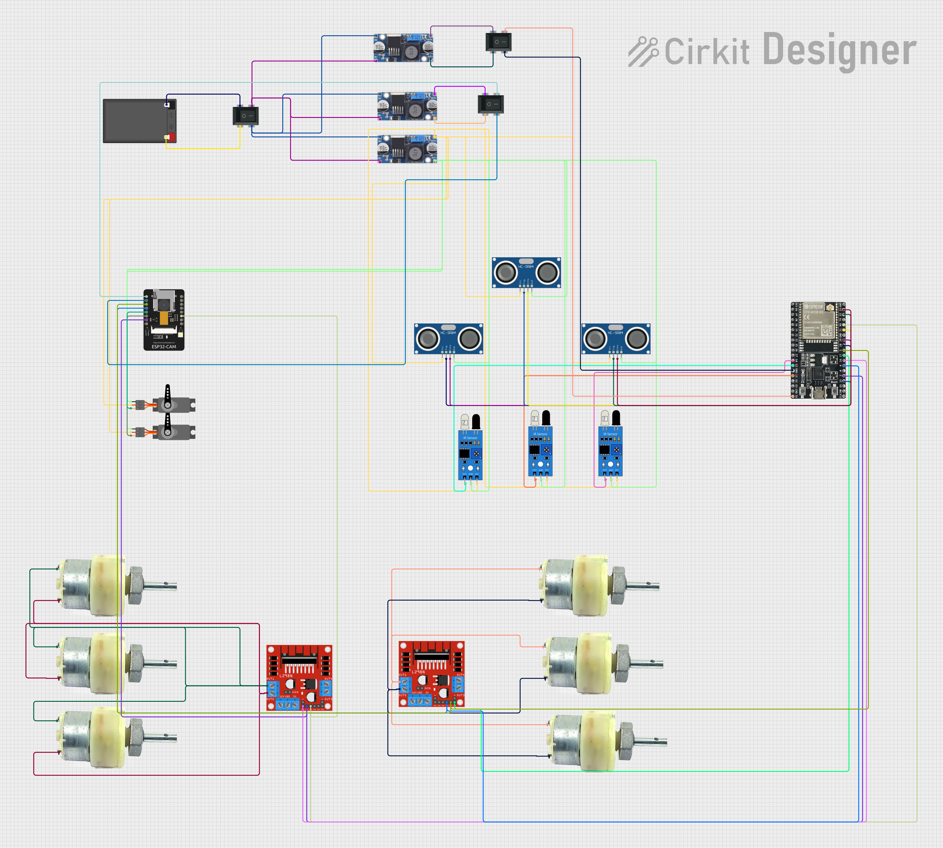
Circuit Documentation
Summary
The circuit in question appears to be a complex system designed to operate a robot car with various sensors and actuators. It includes a power source, voltage regulators, ultrasonic sensors, infrared sensors, servo motors, DC motor drivers, geared motors, rocker switches, an ESP32 microcontroller, and an ESP32-CAM module. The circuit is capable of remote operation and video streaming, with the ESP32-CAM providing a web server for control and video feed.
Component List
Power Components
- 12v 7ah Battery: Provides the main power source for the circuit.
- 48v to 5v Voltage Regulators: Step down the voltage from 48V to 5V to power various low-voltage components.
Sensors
- HC-SR04 Ultrasonic Sensors: Measure distances using ultrasonic waves.
- IR Sensors: Detect objects and changes in the environment using infrared light.
Actuators
- Servo Motors: Control the movement of certain parts, likely for steering or camera orientation.
- 12V Geared Motors: Provide the driving force for the robot car's wheels.
- L298N DC Motor Drivers: Interface between the microcontroller and the motors to control the direction and speed of the motors.
Control Components
- Rocker Switches: Manually open or close the electrical circuit.
Microcontrollers
- ESP32-WROOM-32UE: A powerful microcontroller with Wi-Fi capabilities, used for controlling the robot car and processing sensor data.
- ESP32-CAM: A microcontroller module with an integrated camera, used for video streaming and additional control functions.
Wiring Details
Power Distribution
- 12v 7ah Battery is connected to Rocker Switches to control the power flow to the circuit.
Voltage Regulation
- 48v to 5v Voltage Regulators are wired to the Rocker Switches and provide 5V output to power the low-voltage components.
Sensor Connections
- HC-SR04 Ultrasonic Sensors are connected to the ESP32-WROOM-32UE for distance measurement inputs.
- IR Sensors are connected to the ESP32-WROOM-32UE for object detection inputs.
Actuator Connections
- Servo Motors are controlled by the ESP32-CAM for precise movement.
- 12V Geared Motors are connected to the L298N DC Motor Drivers, which are in turn controlled by the ESP32-WROOM-32UE and ESP32-CAM for movement control.
Control Interfaces
- Rocker Switches are used to manually control the power supply to the Voltage Regulators and the ESP32-CAM.
Documented Code
ESP32-CAM Code Overview
The code for the ESP32-CAM is written in C++ and is designed to handle various tasks such as initializing the camera, setting up a web server for remote control and video streaming, handling HTTP requests, and controlling the servos and LEDs on the robot car. The code includes a comprehensive web interface with buttons and sliders for user interaction.
Key Functions
- Camera Initialization: Sets up the camera with the appropriate GPIO pins and quality settings.
- Web Server Setup: Initializes the web server and registers URI handlers for serving the main page and handling streaming and command requests.
- Command Handling: Processes incoming commands from the web interface to control the robot car's movements, LED brightness, and servo positions.
- Motor Control: Includes functions to move the robot car forward, backward, left, right, and to stop.
Web Interface
The web interface provides a live video stream from the ESP32-CAM and controls for the robot car. It includes buttons for movement, sliders for speed and LED control, and pan/tilt sliders for the camera servos.
Network Configuration
The code includes placeholders for Wi-Fi SSID and password, which need to be replaced with actual network credentials for the ESP32-CAM to connect to a Wi-Fi network.
Error Handling
The code contains error handling for camera initialization failures and HTTP request errors, ensuring that the system can recover from common issues.
Note: The provided code snippet is a high-level overview and does not include the actual code for brevity. The full code would be included in a complete documentation package, along with detailed comments explaining each function and section.