Arduino UNO-Based Automatic Styrofoam Cutter with Dual Stepper Motor Control
Circuit Documentation
Summary
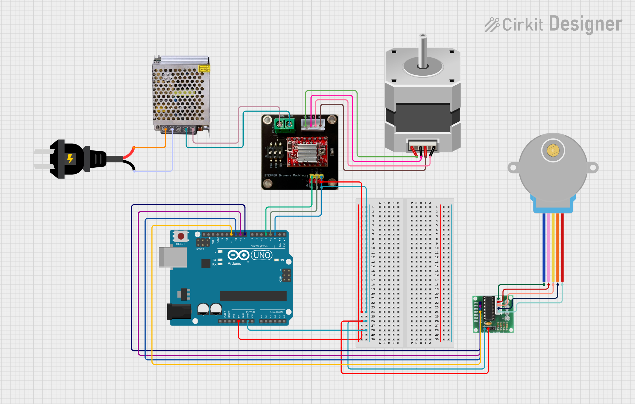
This circuit is designed to control two stepper motors using an Arduino UNO. The circuit includes an A4988 driver for a bipolar stepper motor and a ULN2003 driver for a unipolar stepper motor. The Arduino UNO sends control signals to both drivers to manage the movement of the stepper motors. The power supply provides the necessary voltage for the components.
Component List
Arduino UNO
- Description: Microcontroller board based on the ATmega328P.
- Pins: UNUSED, IOREF, Reset, 3.3V, 5V, GND, Vin, A0, A1, A2, A3, A4, A5, SCL, SDA, AREF, D13, D12, D11, D10, D9, D8, D7, D6, D5, D4, D3, D2, D1, D0
A4988 on Breakout Board
- Description: Stepper motor driver for bipolar stepper motors.
- Pins: VIN (12-24V), GND, 2B, 2A, 1A, 1B, ENABLE, STEP, DIR, VDD (5V)
ULN 2003
- Description: Darlington transistor array for driving unipolar stepper motors.
- Pins: IN1, IN2, IN3, IN4, IN5, IN6, IN7, GND, +, COIL1, COIL2, COIL3, COIL4, COIL5
28BYJ-48 Stepper Motor
- Description: Unipolar stepper motor.
- Pins: BLUE, PINK, YELLOW, ORANGE, RED
Stepper Motor (Bipolar)
- Description: Bipolar stepper motor.
- Pins: D, B, C, A
POWER SUPPLY 12V 5AMP
- Description: Power supply providing 12V DC output.
- Pins: 220V Positive Pole (AC), 220V Negative Pole (AC), GND, GND (DC), 12V-24V Output (DC)
AC source
- Description: AC power source.
- Pins: +, -
Wiring Details
Arduino UNO
- 5V connected to VDD (5V) of A4988 on Breakout Board and + of ULN 2003.
- GND connected to GND of A4988 on Breakout Board and GND of ULN 2003.
- D11 connected to IN4 of ULN 2003.
- D10 connected to IN3 of ULN 2003.
- D9 connected to IN2 of ULN 2003.
- D8 connected to IN1 of ULN 2003.
- D4 connected to ENABLE of A4988 on Breakout Board.
- D3 connected to STEP of A4988 on Breakout Board.
- D2 connected to DIR of A4988 on Breakout Board.
A4988 on Breakout Board
- VIN (12-24V) connected to 12V-24V Output (DC) of POWER SUPPLY 12V 5AMP.
- GND connected to GND (DC) of POWER SUPPLY 12V 5AMP.
- 2B connected to A of Stepper Motor (Bipolar).
- 2A connected to C of Stepper Motor (Bipolar).
- 1A connected to D of Stepper Motor (Bipolar).
- 1B connected to B of Stepper Motor (Bipolar).
ULN 2003
- COIL1 connected to BLUE of 28BYJ-48 Stepper Motor.
- COIL2 connected to PINK of 28BYJ-48 Stepper Motor.
- COIL3 connected to YELLOW of 28BYJ-48 Stepper Motor.
- COIL4 connected to ORANGE of 28BYJ-48 Stepper Motor.
- COIL5 connected to RED of 28BYJ-48 Stepper Motor.
POWER SUPPLY 12V 5AMP
- 220V Positive Pole (AC) connected to + of AC source.
- 220V Negative Pole (AC) connected to - of AC source.
Code Documentation
/*
 * Arduino Sketch for Automatic Styrofoam Cutter
 * This code controls two stepper motors using an A4988 driver and a ULN2003 driver.
 * The A4988 driver controls a bipolar stepper motor, while the ULN2003 driver
 * controls a unipolar stepper motor. The Arduino UNO is used to send control
 * signals to both drivers. The code initializes the pins and runs a simple
 * sequence to demonstrate the movement of the stepper motors.
 */

// Pin definitions for ULN2003 driver
#define IN1 8
#define IN2 9
#define IN3 10
#define IN4 11

// Pin definitions for A4988 driver
#define DIR_PIN 2
#define STEP_PIN 3
#define ENABLE_PIN 4

void setup() {
  // Initialize serial communication
  Serial.begin(9600);

  // Set ULN2003 pins as outputs
  pinMode(IN1, OUTPUT);
  pinMode(IN2, OUTPUT);
  pinMode(IN3, OUTPUT);
  pinMode(IN4, OUTPUT);

  // Set A4988 pins as outputs
  pinMode(DIR_PIN, OUTPUT);
  pinMode(STEP_PIN, OUTPUT);
  pinMode(ENABLE_PIN, OUTPUT);

  // Enable A4988 driver
  digitalWrite(ENABLE_PIN, LOW);
}

void loop() {
  // Rotate unipolar stepper motor (ULN2003) one full cycle
  for (int i = 0; i < 512; i++) {
    stepUnipolar();
  }

  // Rotate bipolar stepper motor (A4988) one full cycle
  digitalWrite(DIR_PIN, HIGH); // Set direction
  for (int i = 0; i < 200; i++) {
    stepBipolar();
  }

  delay(1000); // Wait for 1 second
}

void stepUnipolar() {
  digitalWrite(IN1, HIGH);
  digitalWrite(IN2, LOW);
  digitalWrite(IN3, LOW);
  digitalWrite(IN4, LOW);
  delay(2);
  digitalWrite(IN1, LOW);
  digitalWrite(IN2, HIGH);
  digitalWrite(IN3, LOW);
  digitalWrite(IN4, LOW);
  delay(2);
  digitalWrite(IN1, LOW);
  digitalWrite(IN2, LOW);
  digitalWrite(IN3, HIGH);
  digitalWrite(IN4, LOW);
  delay(2);
  digitalWrite(IN1, LOW);
  digitalWrite(IN2, LOW);
  digitalWrite(IN3, LOW);
  digitalWrite(IN4, HIGH);
  delay(2);
}

void stepBipolar() {
  digitalWrite(STEP_PIN, HIGH);
  delayMicroseconds(1000);
  digitalWrite(STEP_PIN, LOW);
  delayMicroseconds(1000);
}
This code initializes the pins for the ULN2003 and A4988 drivers and runs a simple sequence to rotate both the unipolar and bipolar stepper motors. The stepUnipolar function controls the ULN2003 driver, while the stepBipolar function controls the A4988 driver. The main loop rotates each motor one full cycle and then waits for one second before repeating.