
Light-Activated LED Control Circuit with LM358 Op-Amp and BC547 Transistor
View and Edit Project In Cirkit Designer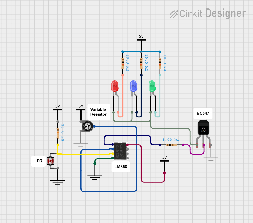
Circuit Documentation
Summary
The circuit in question appears to be an analog circuit that utilizes an LM358 operational amplifier (op-amp) in conjunction with a photocell (LDR), resistors, a trimmer potentiometer, a BC547 transistor, and multiple LEDs (red, green, and blue). The circuit likely functions as a light-sensitive switch or indicator, where the photocell's resistance changes with light intensity, which in turn affects the op-amp's output. This output can drive the BC547 transistor to switch the LEDs on or off. The trimmer potentiometer allows for adjustment of the sensitivity of the circuit.
Component List
- Photocell (LDR): A light-dependent resistor whose resistance varies with light intensity.
- Resistors: Passive components used to limit current or divide voltages in the circuit. Multiple resistors with different resistance values are used.
- LEDs (Red, Green, Blue): Light Emitting Diodes that emit red, green, or blue light when forward-biased.
- Trimmer Potentiometer: A variable resistor with three terminals, used to adjust circuit parameters.
- BC547 Transistor: An NPN bipolar junction transistor used as a switch or amplifier.
- LM358 Op-Amp: A dual operational amplifier used for signal amplification or other analog functions.
- Vcc: Represents the positive supply voltage to the circuit.
- GND: Represents the ground or zero-voltage reference point in the circuit.
Wiring Details
Photocell (LDR)
- Pin 0: Not connected in the provided net list.
- Pin 1: Connected to pin 3 of the LM358 Op-Amp and pin 2 of a 10k Ohm resistor.
Resistors
- 10k Ohm Resistors:
- One end connected to the photocell and LM358 Op-Amp.
- One end connected to the anode of the red LED.
- One end connected to the anode of the blue LED.
- One end connected to the anode of the green LED.
- One end connected to the wiper of the trimmer potentiometer.
- 1k Ohm Resistor:
- One end connected to pin 1 of the LM358 Op-Amp.
- The other end connected to the base of the BC547 Transistor.
LEDs
- Red LED:
- Anode: Connected to a 10k Ohm resistor.
- Cathode: Common cathode connection with green and blue LEDs to the collector of the BC547 Transistor.
- Green LED:
- Anode: Connected to a 10k Ohm resistor.
- Cathode: Common cathode connection with red and blue LEDs to the collector of the BC547 Transistor.
- Blue LED:
- Anode: Connected to a 10k Ohm resistor.
- Cathode: Common cathode connection with red and green LEDs to the collector of the BC547 Transistor.
Trimmer Potentiometer
- Leg 1: Not connected in the provided net list.
- Wiper: Connected to pin 2 of the LM358 Op-Amp.
- Leg 2: Not connected in the provided net list.
BC547 Transistor
- Collector: Connected to the cathodes of the red, green, and blue LEDs.
- Base: Connected to a 1k Ohm resistor.
- Emitter: Not connected in the provided net list.
LM358 Op-Amp
- Pin 1: Connected to a 1k Ohm resistor.
- Pin 2: Connected to the wiper of the trimmer potentiometer.
- Pin 3: Connected to the photocell and a 10k Ohm resistor.
- Pin 4: Connected to GND.
- Pin 8: Connected to Vcc.
- Pins 5, 6, 7: Not connected in the provided net list.
Vcc
- Represents the positive supply voltage and is connected to pin 8 of the LM358 Op-Amp.
GND
- Represents the ground reference and is connected to pin 4 of the LM358 Op-Amp.
Documented Code
No code was provided for any microcontrollers in the circuit. This section is not applicable.
Please note that the wiring details are based on the provided electrical net list and may not represent the complete circuit functionality. Additional connections, such as power supply connections to Vcc and GND for the LEDs and the transistor, are not specified in the net list but are necessary for the circuit to function properly.