
Arduino UNO Controlled Dual Stepper Motor System with LED Indicator and Kill Switch
View and Edit Project In Cirkit Designer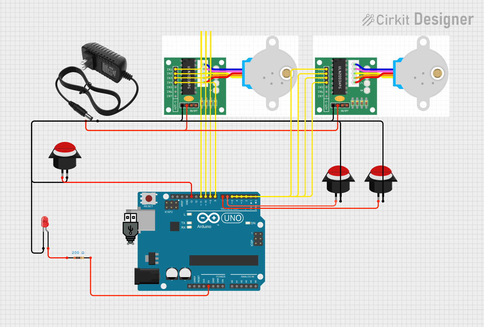
Circuit Documentation
Summary
This circuit is designed to control two stepper motors and an LED using an Arduino UNO. The circuit includes three push buttons: two for controlling the stepper motors and one as a kill switch to cut power to the Arduino. The LED is always on when the circuit is powered.
Component List
Arduino UNO
- Description: Microcontroller board based on the ATmega328P.
- Pins: UNUSED, IOREF, Reset, 3.3V, 5V, GND, Vin, A0, A1, A2, A3, A4, A5, SCL, SDA, AREF, D13, D12, D11, D10, D9, D8, D7, D6, D5, D4, D3, D2, D1, D0
Stepper Motor One
- Description: Stepper motor with four control pins and two power pins.
- Pins: IN1, IN2, IN3, IN4, +, -
Stepper Motor Two
- Description: Stepper motor with four control pins and two power pins.
- Pins: IN1, IN2, IN3, IN4, +, -
12V Power Supply
- Description: Power supply providing 12V.
- Pins: +, -
USB Power
- Description: Power supply via USB.
- Pins: +, -
Push Button Round (Button 1)
- Description: Push button switch.
- Pins: leg0, leg1
Push Button Round (Button 2)
- Description: Push button switch.
- Pins: leg0, leg1
Push Button Round (Kill Switch)
- Description: Push button switch.
- Pins: leg0, leg1
LED: Two Pin (Red)
- Description: Red LED.
- Pins: cathode, anode
Resistor
- Description: Resistor with a resistance of 200 Ohms.
- Pins: pin1, pin2
Wiring Details
Arduino UNO
- 5V connected to Resistor pin2
- D13 connected to Push Button Round (Kill Switch) leg0
- D11 connected to Stepper Motor One IN1
- D10 connected to Stepper Motor One IN2
- D9 connected to Stepper Motor One IN3
- D8 connected to Stepper Motor One IN4
- D7 connected to Push Button Round (Button 2) leg0
- D6 connected to Push Button Round (Button 1) leg0
- D5 connected to Stepper Motor Two IN1
- D4 connected to Stepper Motor Two IN2
- D3 connected to Stepper Motor Two IN3
- D2 connected to Stepper Motor Two IN4
Stepper Motor One
- IN1 connected to Arduino UNO D11
- IN2 connected to Arduino UNO D10
- IN3 connected to Arduino UNO D9
- IN4 connected to Arduino UNO D8
- + connected to 12V Power Supply +
- - connected to 12V Power Supply -
Stepper Motor Two
- IN1 connected to Arduino UNO D5
- IN2 connected to Arduino UNO D4
- IN3 connected to Arduino UNO D3
- IN4 connected to Arduino UNO D2
- + connected to 12V Power Supply +
- - connected to 12V Power Supply -
12V Power Supply
- + connected to Stepper Motor One + and Stepper Motor Two +
- - connected to Stepper Motor One - and Stepper Motor Two -
Push Button Round (Button 1)
- leg0 connected to Arduino UNO D6
- leg1 connected to 12V Power Supply -
Push Button Round (Button 2)
- leg0 connected to Arduino UNO D7
- leg1 connected to 12V Power Supply -
Push Button Round (Kill Switch)
- leg0 connected to Arduino UNO D13
- leg1 connected to 12V Power Supply -
LED: Two Pin (Red)
- cathode connected to 12V Power Supply -
- anode connected to Resistor pin1
Resistor
- pin1 connected to LED: Two Pin (Red) anode
- pin2 connected to Arduino UNO 5V
Code Documentation
/*
 * This Arduino sketch controls two stepper motors and an LED. The two buttons
 * on the right, when pressed, will turn the corresponding stepper motor. The
 * leftmost switch is a kill switch that will cut power to the Arduino. The LED
 * will be on at all times.
 */

// Pin definitions
const int button1Pin = 6;
const int button2Pin = 7;
const int killSwitchPin = 13;
const int ledPin = 13;

// Stepper motor 1 pins
const int stepper1Pin1 = 11;
const int stepper1Pin2 = 10;
const int stepper1Pin3 = 9;
const int stepper1Pin4 = 8;

// Stepper motor 2 pins
const int stepper2Pin1 = 5;
const int stepper2Pin2 = 4;
const int stepper2Pin3 = 3;
const int stepper2Pin4 = 2;

void setup() {
  // Initialize button pins as inputs
  pinMode(button1Pin, INPUT);
  pinMode(button2Pin, INPUT);
  pinMode(killSwitchPin, INPUT);

  // Initialize LED pin as output
  pinMode(ledPin, OUTPUT);

  // Initialize stepper motor pins as outputs
  pinMode(stepper1Pin1, OUTPUT);
  pinMode(stepper1Pin2, OUTPUT);
  pinMode(stepper1Pin3, OUTPUT);
  pinMode(stepper1Pin4, OUTPUT);
  pinMode(stepper2Pin1, OUTPUT);
  pinMode(stepper2Pin2, OUTPUT);
  pinMode(stepper2Pin3, OUTPUT);
  pinMode(stepper2Pin4, OUTPUT);

  // Turn on the LED
  digitalWrite(ledPin, HIGH);
}

void loop() {
  // Check if kill switch is pressed
  if (digitalRead(killSwitchPin) == HIGH) {
    // Turn off the Arduino (simulate by stopping execution)
    while (true) {}
  }

  // Check if button 1 is pressed
  if (digitalRead(button1Pin) == HIGH) {
    // Turn stepper motor 1
    stepperMotor1();
  }

  // Check if button 2 is pressed
  if (digitalRead(button2Pin) == HIGH) {
    // Turn stepper motor 2
    stepperMotor2();
  }
}

void stepperMotor1() {
  // Simple stepper motor sequence for motor 1
  digitalWrite(stepper1Pin1, HIGH);
  digitalWrite(stepper1Pin2, LOW);
  digitalWrite(stepper1Pin3, LOW);
  digitalWrite(stepper1Pin4, LOW);
  delay(10);
  digitalWrite(stepper1Pin1, LOW);
  digitalWrite(stepper1Pin2, HIGH);
  digitalWrite(stepper1Pin3, LOW);
  digitalWrite(stepper1Pin4, LOW);
  delay(10);
  digitalWrite(stepper1Pin1, LOW);
  digitalWrite(stepper1Pin2, LOW);
  digitalWrite(stepper1Pin3, HIGH);
  digitalWrite(stepper1Pin4, LOW);
  delay(10);
  digitalWrite(stepper1Pin1, LOW);
  digitalWrite(stepper1Pin2, LOW);
  digitalWrite(stepper1Pin3, LOW);
  digitalWrite(stepper1Pin4, HIGH);
  delay(10);
}

void stepperMotor2() {
  // Simple stepper motor sequence for motor 2
  digitalWrite(stepper2Pin1, HIGH);
  digitalWrite(stepper2Pin2, LOW);
  digitalWrite(stepper2Pin3, LOW);
  digitalWrite(stepper2Pin4, LOW);
  delay(10);
  digitalWrite(stepper2Pin1, LOW);
  digitalWrite(stepper2Pin2, HIGH);
  digitalWrite(stepper2Pin3, LOW);
  digitalWrite(stepper2Pin4, LOW);
  delay(10);
  digitalWrite(stepper2Pin1, LOW);
  digitalWrite(stepper2Pin2, LOW);
  digitalWrite(stepper2Pin3, HIGH);
  digitalWrite(stepper2Pin4, LOW);
  delay(10);
  digitalWrite(stepper2Pin1, LOW);
  digitalWrite(stepper2Pin2, LOW);
  digitalWrite(stepper2Pin3, LOW);
  digitalWrite(stepper2Pin4, HIGH);
  delay(10);
}
This code initializes the pins for the buttons, LED, and