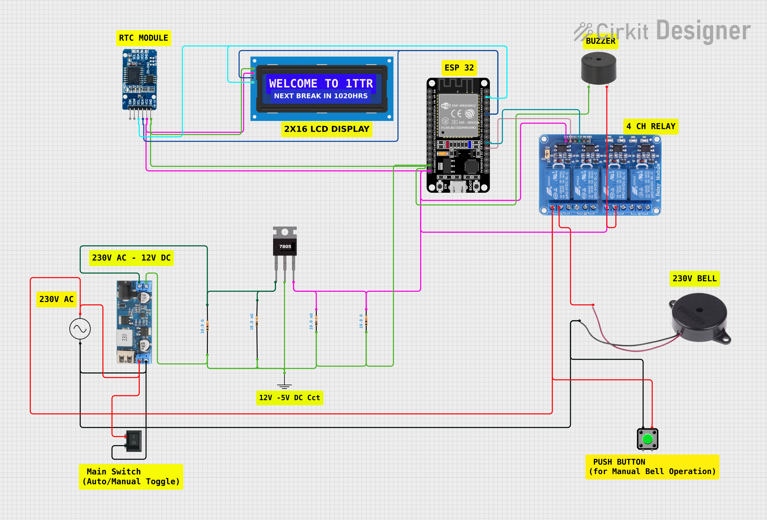
ESP32-Controlled Time-Triggered Relay System with LCD Feedback

Circuit Documentation
Summary of the Circuit
This circuit appears to be designed for timekeeping and control applications, featuring an ESP32 microcontroller, an RTC DS3231 for real-time clock functionality, a 4-channel 5V relay module for controlling external devices, two buzzers for audio signaling, and an LCD screen with I2C interface for display purposes. The circuit also includes a 7805 voltage regulator, a 12V to 5V step-down power converter, and various resistors for voltage/current adjustments. A rocker switch and a pushbutton are included for user interaction. The power supply is an AC source, which is stepped down and regulated for the circuit's requirements.
Component List
ESP32 (30 pin)
- Microcontroller with WiFi and Bluetooth capabilities.
- 30 GPIO pins including analog inputs, digital I/O, UART, I2C, and power pins.
RTC DS3231
- Real-time clock module for timekeeping.
- Includes pins for I2C communication and power.
Relay 4 Channel 5v
- 4-channel relay module for controlling high power devices.
- Includes input pins for control signals, common (COM), normally open (NO), and normally closed (NC) contacts for each channel.
Buzzer
- Audio signaling device.
- Includes a positive and a ground pin.
LCD screen 16x2 I2C
- Alphanumeric liquid crystal display with 16 characters by 2 lines.
- I2C interface for communication.
Pushbutton
- A momentary pushbutton switch.
- Four pins for switch connections.
7805
- Voltage regulator providing a 5V output.
- Three pins for input voltage, ground, and output voltage.
Resistor
- Passive component used to limit current or divide voltages.
- Two pins for electrical connection.
12v to 5v Step Down Power Converter
- Converts input voltages from 9V-36V to a stable 5V output.
- Multiple pins for input, output, and ground connections.
AC Supply
- Provides alternating current power supply.
- Two pins for positive and negative voltage.
Rocker Switch (SPST)
- Single Pole Single Throw (SPST) rocker switch.
- Two pins for switch connections.
Wiring Details
ESP32 (30 pin)
GNDconnected to the common ground net.Vinconnected to the 5V power net.D22(SCL) andD21(SDA) connected to the I2C bus for communication with RTC and LCD.RX2connected to Relay 4 Channel 5vIN2.D4connected to Relay 4 Channel 5vIN4.
RTC DS3231
GNDconnected to the common ground net.VCCconnected to the 5V power net.SCLandSDAconnected to the I2C bus for communication with ESP32 and LCD.
Relay 4 Channel 5v
GNDconnected to the common ground net.VCCconnected to the 5V power net.IN2controlled by ESP32RX2.IN4controlled by ESP32D4.NO2connected to one terminal of the buzzer.COM2connected to the other terminal of the buzzer.COM4connected to the positive terminal of the second buzzer.
Buzzer
- One terminal connected to
NO2of Relay 4 Channel 5v. - The other terminal connected to the common ground net.
LCD screen 16x2 I2C
GNDconnected to the common ground net.VCCconnected to the 5V power net.SCLandSDAconnected to the I2C bus for communication with ESP32 and RTC.
Pushbutton
- One terminal (
Pin 4) connected to the AC supply positive. - The other terminal (
Pin 1) connected to the negative terminal of the second buzzer.
7805
Gndconnected to the common ground net.Vinconnected to the 12V power net.Voutconnected to the 5V power net.
Resistor
- Multiple resistors used in the circuit for various purposes, connected between different components and nets.
12v to 5v Step Down Power Converter
VIN+connected to the 12V power net.VIN-andGNDconnected to the common ground net.5v OUTPUTproviding the 5V power net.
AC Supply
+veconnected to the positive terminal of the step-down converter and one terminal of the pushbutton.-veconnected to the negative terminal of the second buzzer and the common ground net.
Rocker Switch (SPST)
- One terminal connected to the AC supply positive.
- The other terminal connected to the positive terminal of the step-down converter.
Documented Code
There is no code provided for the microcontroller(s) in the circuit. If code is available, it should be documented here with explanations of how it interacts with the hardware components, including setup, main loop, and any interrupt service routines or functions.