Cirkit Designer
Your all-in-one circuit design IDE
Home /
Project Documentation
Arduino UNO-Based Water Level and Distance Monitoring System with LED Indicator
Circuit Documentation
Summary
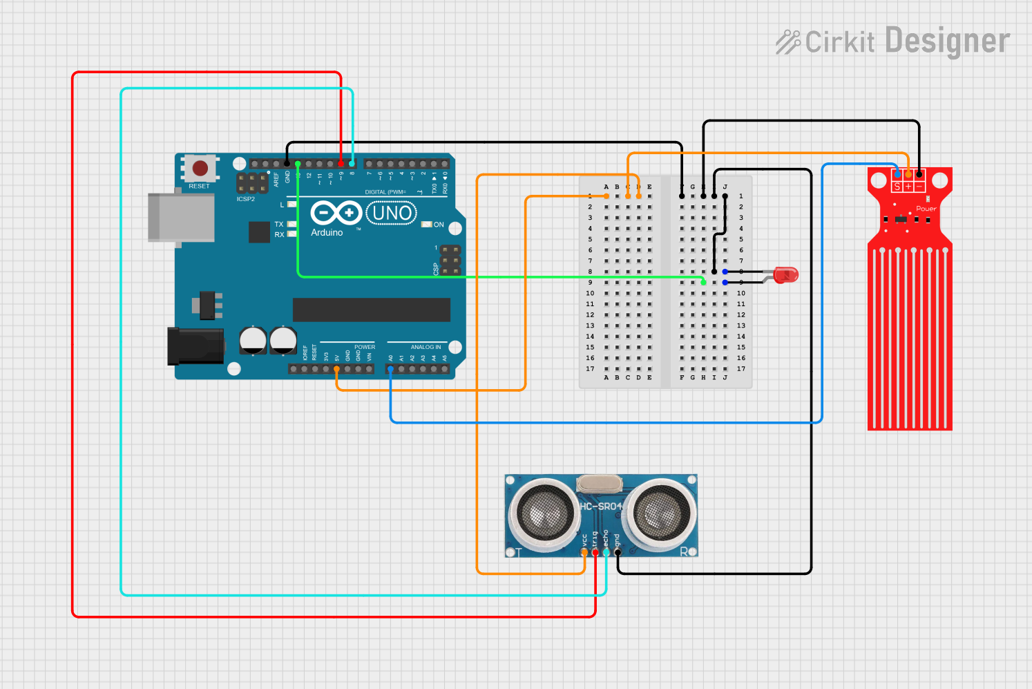
This circuit involves an Arduino UNO microcontroller interfacing with a red LED, a water level sensor, and an ultrasonic sensor. The Arduino UNO reads data from the water level sensor and the ultrasonic sensor, and controls the LED based on serial input.
Component List
Arduino UNO
- Description: A microcontroller board based on the ATmega328P.
- Pins: UNUSED, IOREF, Reset, 3.3V, 5V, GND, Vin, A0, A1, A2, A3, A4, A5, SCL, SDA, AREF, D13, D12, D11, D10, D9, D8, D7, D6, D5, D4, D3, D2, D1, D0
LED: Two Pin (red)
- Description: A red LED with two pins.
- Pins: cathode, anode
Water Level Sensor
- Description: A sensor to measure water level.
- Pins: SIG, VCC, GND
Ultrasonic Sensor
- Description: A sensor to measure distance using ultrasonic waves.
- Pins: +VCC, Trigger, Echo, GND
Wiring Details
Arduino UNO
- 5V: Connected to +VCC of the Ultrasonic Sensor and VCC of the Water Level Sensor.
- GND: Connected to the cathode of the LED, GND of the Ultrasonic Sensor, and GND of the Water Level Sensor.
- D13: Connected to the anode of the LED.
- A0: Connected to SIG of the Water Level Sensor.
- D9: Connected to Trigger of the Ultrasonic Sensor.
- D8: Connected to Echo of the Ultrasonic Sensor.
LED: Two Pin (red)
- cathode: Connected to GND of the Arduino UNO.
- anode: Connected to D13 of the Arduino UNO.
Water Level Sensor
- SIG: Connected to A0 of the Arduino UNO.
- VCC: Connected to 5V of the Arduino UNO.
- GND: Connected to GND of the Arduino UNO.
Ultrasonic Sensor
- +VCC: Connected to 5V of the Arduino UNO.
- Trigger: Connected to D9 of the Arduino UNO.
- Echo: Connected to D8 of the Arduino UNO.
- GND: Connected to GND of the Arduino UNO.
Code Documentation
Arduino UNO Code
char Incoming_value='B';
int pin13=13;
int LEVEL = 0;

void setup()
{
  Serial.begin(9600);
  pinMode(pin13, OUTPUT);
  pinMode(A0, INPUT);
  LEVEL = analogRead(A0);
}

void loop()
{
  LEVEL = analogRead(A0);
  if(Serial.available()>0)
  {
    Incoming_value = Serial.read();
    Serial.print(Incoming_value);
    Serial.print("\n");
    if(Incoming_value == 'A')
      digitalWrite(pin13, HIGH);
    else if(Incoming_value == 'B')
      digitalWrite(pin13, LOW);
  }
  Serial.println(LEVEL);
  delay(500);
}
Code Explanation
Variables:
Incoming_value: Stores the incoming serial data.pin13: Represents the digital pin 13 on the Arduino UNO.LEVEL: Stores the analog value read from the water level sensor.
setup():
- Initializes serial communication at 9600 baud rate.
- Sets
pin13as an output pin. - Sets
A0as an input pin. - Reads the initial value from the water level sensor.
loop():
- Continuously reads the value from the water level sensor.
- Checks if there is any incoming serial data.
- If the incoming data is 'A', it turns on the LED connected to pin 13.
- If the incoming data is 'B', it turns off the LED connected to pin 13.
- Prints the water level sensor value to the serial monitor.
- Delays for 500 milliseconds before repeating the loop.