
Arduino UNO-Based Environmental Monitoring System with GSM Alert
View and Edit Project In Cirkit Designer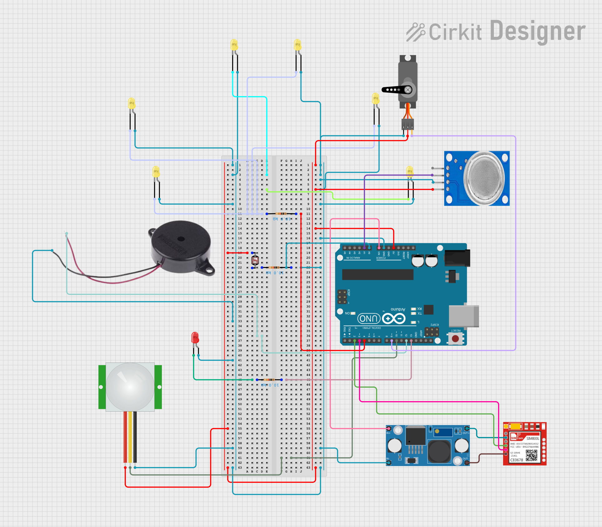
Circuit Documentation
Summary
This circuit is designed to interface various components with an Arduino UNO microcontroller. It includes a GSM module (Sim800l), multiple yellow and one red LED, a PIR sensor, a photocell (LDR), a buzzer, a servo motor, an MQ135 air quality sensor, and a step-down (buck) converter (LM2596). The circuit appears to be a multifunctional system capable of sensing and responding to environmental changes, possibly for home automation or security purposes.
Component List
Microcontroller
- Arduino UNO: A microcontroller board based on the ATmega328P, with a variety of digital and analog I/O pins.
Sensors
- PIR sensor: A motion sensor that detects changes in infrared levels caused by moving objects.
- Photocell (LDR): A light-dependent resistor that changes resistance based on light intensity.
- MQ135: An air quality sensor for detecting a wide range of gases, including NH3, NOx, alcohol, benzene, smoke, and CO2.
Communication Module
- Sim800l: A GSM/GPRS module that allows cellular network connectivity for voice, SMS, and data.
Power Module
- LM2596 Step Down Module: A DC-DC buck converter that steps down voltage while maintaining a constant output current.
Actuator
- Servo: A rotary actuator that allows for precise control of angular position.
Indicators and Sound
- LED: Two Pin (yellow): Yellow light-emitting diodes used as visual indicators.
- LED: Two Pin (red): A red light-emitting diode used as a visual indicator.
- Buzzer: An electronic sounder that can be used to generate tones or alerts.
Passive Components
- Resistor: A passive two-terminal electrical component that implements electrical resistance as a circuit element.
Wiring Details
Arduino UNO
- Digital Pin 4 (D4) connected to a 10k Ohm resistor.
- Digital Pin 9 (D9) connected to the PWM input of the Servo.
- Digital Pin 10 (D10) connected to the SIG pin of the PIR sensor.
- Digital Pin 12 (D12) connected to the POSITIVE pin of the Buzzer.
- Digital Pin 13 (D13) connected to a 10k Ohm resistor leading to the cathode of the red LED.
- Analog Pin 0 (A0) connected to a 10k Ohm resistor and the Photocell (LDR).
- Analog Pin 1 (A1) connected to the A0 pin of the MQ135 sensor.
- Digital Pin 2 (D2) connected to the RXD pin of the Sim800l.
- Digital Pin 3 (D3) connected to the TXD pin of the Sim800l.
- 5V pin providing power to the Photocell (LDR), PIR sensor, Servo, and MQ135 sensor.
- GND pin connected to the common ground of the circuit.
- Vin pin connected to the IN+ pin of the LM2596 Step Down Module.
Sim800l
- VCC connected to the OUT+ of the LM2596 Step Down Module.
- GND connected to the common ground of the circuit.
LM2596 Step Down Module
- IN- connected to the common ground of the circuit.
- IN+ connected to the Vin pin of the Arduino UNO.
- OUT- connected to the common ground of the circuit.
- OUT+ providing power to the Sim800l.
LEDs (Yellow and Red)
- Anodes connected to the common ground through their respective resistors.
- Cathodes of yellow LEDs connected to the common ground directly.
PIR Sensor
- VDD connected to the 5V pin of the Arduino UNO.
- SIG connected to Digital Pin 10 (D10) of the Arduino UNO.
- GND connected to the common ground of the circuit.
Photocell (LDR)
- One pin connected to the 5V pin of the Arduino UNO.
- The other pin connected to Analog Pin 0 (A0) of the Arduino UNO through a 10k Ohm resistor.
Buzzer
- POSITIVE connected to Digital Pin 12 (D12) of the Arduino UNO.
- NEGATIVE connected to the common ground of the circuit.
Servo
- VCC connected to the 5V pin of the Arduino UNO.
- GND connected to the common ground of the circuit.
- PWM connected to Digital Pin 9 (D9) of the Arduino UNO.
MQ135 Sensor
- VCC connected to the 5V pin of the Arduino UNO.
- GND connected to the common ground of the circuit.
- A0 connected to Analog Pin 1 (A1) of the Arduino UNO.
Documented Code
Arduino UNO Code (sketch.ino)
void setup() {
  // put your setup code here, to run once:

}

void loop() {
  // put your main code here, to run repeatedly:

}
Note: The provided code is a template and does not include any functionality. It needs to be populated with the logic to control and interact with the connected components based on the requirements of the application.