
Arduino-Powered RC Tank with L298N Motor Driver and LiPo Battery
View and Edit Project In Cirkit Designer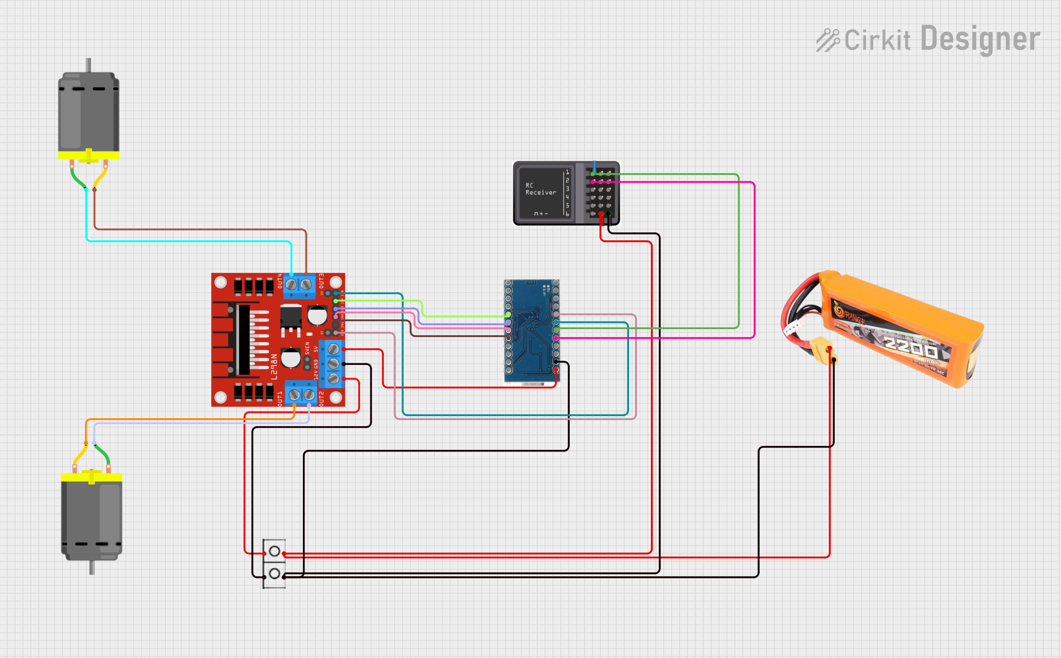
Circuit Documentation
Summary
This circuit is designed to control an RC tank using an Arduino Micro Pro, an L298N motor driver, and an RC receiver module. The Arduino receives input signals from the RC receiver and controls the motor driver to drive two DC motors. The power is supplied by a LiPo battery.
Component List
LiPo Battery 2200mAH 30C
- Description: Provides power to the circuit.
- Pins: VCC, GND
Arduino Micro Pro
- Description: Microcontroller that processes input signals and controls the motor driver.
- Pins: RAW, RST, VCC, A3, A2, A1, A0, 15, 14, 16, 10, 9, 8, 7, 6, 5, 4, 3, 2, GND, RX, TX
L298N DC Motor Driver
- Description: Drives the DC motors based on signals from the Arduino.
- Pins: OUT1, OUT2, 12V, GND, 5V, OUT3, OUT4, 5V-ENA-JMP-I, 5V-ENA-JMP-O, +5V-J1, +5V-J2, ENA, IN1, IN2, IN3, IN4, ENB
DC Motor
- Description: Motors that drive the RC tank.
- Pins: pin 1, pin 2
Wire Connector
- Description: Connects the power supply to the circuit.
- Pins: +, -
RC Receiver Module
- Description: Receives control signals from the RC transmitter.
- Pins: S6, S5, S4, S3, S2, S1, Vcc, GND
Wiring Details
LiPo Battery 2200mAH 30C
VCC is connected to:
- Wire Connector (+)
- RC Receiver Module (Vcc)
GND is connected to:
- Wire Connector (-)
- RC Receiver Module (GND)
- Arduino Micro Pro (GND)
Arduino Micro Pro
RAW is connected to L298N DC Motor Driver (5V)
GND is connected to:
- Wire Connector (-)
- RC Receiver Module (GND)
- LiPo Battery 2200mAH 30C (GND)
A3 is connected to RC Receiver Module (S2)
A2 is connected to RC Receiver Module (S1)
A1 is connected to L298N DC Motor Driver (ENB)
A0 is connected to L298N DC Motor Driver (ENA)
5 is connected to L298N DC Motor Driver (IN4)
4 is connected to L298N DC Motor Driver (IN3)
3 is connected to L298N DC Motor Driver (IN2)
2 is connected to L298N DC Motor Driver (IN1)
L298N DC Motor Driver
5V is connected to Arduino Micro Pro (RAW)
ENA is connected to Arduino Micro Pro (A0)
ENB is connected to Arduino Micro Pro (A1)
IN1 is connected to Arduino Micro Pro (2)
IN2 is connected to Arduino Micro Pro (3)
IN3 is connected to Arduino Micro Pro (4)
IN4 is connected to Arduino Micro Pro (5)
OUT1 is connected to DC Motor (pin 2)
OUT2 is connected to DC Motor (pin 1)
OUT3 is connected to DC Motor (pin 2)
OUT4 is connected to DC Motor (pin 1)
12V is connected to Wire Connector (+)
GND is connected to Wire Connector (-)
DC Motor
pin 1 is connected to L298N DC Motor Driver (OUT2)
pin 2 is connected to L298N DC Motor Driver (OUT1)
pin 1 is connected to L298N DC Motor Driver (OUT4)
pin 2 is connected to L298N DC Motor Driver (OUT3)
Wire Connector
+ is connected to:
- LiPo Battery 2200mAH 30C (VCC)
- RC Receiver Module (Vcc)
- L298N DC Motor Driver (12V)
- is connected to:
- LiPo Battery 2200mAH 30C (GND)
- RC Receiver Module (GND)
- Arduino Micro Pro (GND)
- L298N DC Motor Driver (GND)
RC Receiver Module
Vcc is connected to:
- Wire Connector (+)
- LiPo Battery 2200mAH 30C (VCC)
GND is connected to:
- Wire Connector (-)
- LiPo Battery 2200mAH 30C (GND)
- Arduino Micro Pro (GND)
S2 is connected to Arduino Micro Pro (A3)
S1 is connected to Arduino Micro Pro (A2)
Code Documentation
/*
 * RC Tank Control
 * This sketch controls an RC tank with forward, backward, and speed control.
 * The RC receiver module provides input signals to the Arduino.
 * The Arduino controls the L298N motor driver to drive the motors.
 */

// Pin definitions
const int ENA = A0;
const int ENB = A1;
const int IN1 = 2;
const int IN2 = 3;
const int IN3 = 4;
const int IN4 = 5;
const int RC_CH1 = A2; // Channel 1 from RC Receiver
const int RC_CH2 = A3; // Channel 2 from RC Receiver

void setup() {
  // Initialize motor control pins
  pinMode(ENA, OUTPUT);
  pinMode(ENB, OUTPUT);
  pinMode(IN1, OUTPUT);
  pinMode(IN2, OUTPUT);
  pinMode(IN3, OUTPUT);
  pinMode(IN4, OUTPUT);
  // Initialize RC receiver input pins
  pinMode(RC_CH1, INPUT);
  pinMode(RC_CH2, INPUT);
}

void loop() {
  int ch1 = pulseIn(RC_CH1, HIGH);
  int ch2 = pulseIn(RC_CH2, HIGH);

  // Determine motor speed and direction
  int speedA = map(ch1, 1000, 2000, 0, 255);
  int speedB = map(ch2, 1000, 2000, 0, 255);

  // Forward or backward control
  if (ch1 > 1500) {
    digitalWrite(IN1, HIGH);
    digitalWrite(IN2, LOW);
  } else {
    digitalWrite(IN1, LOW);
    digitalWrite(IN2, HIGH);
  }

  if (ch2 > 1500) {
    digitalWrite(IN3, HIGH);
    digitalWrite(IN4, LOW);
  } else {
    digitalWrite(IN3, LOW);
    digitalWrite(IN4, HIGH);
  }

  // Set motor speeds
  analogWrite(ENA, speedA);
  analogWrite(ENB, speedB);
}
This code initializes the pins for motor control and RC receiver input. In the loop function, it reads the input signals from the RC receiver, maps them to motor speeds, and sets the motor direction and speed accordingly.