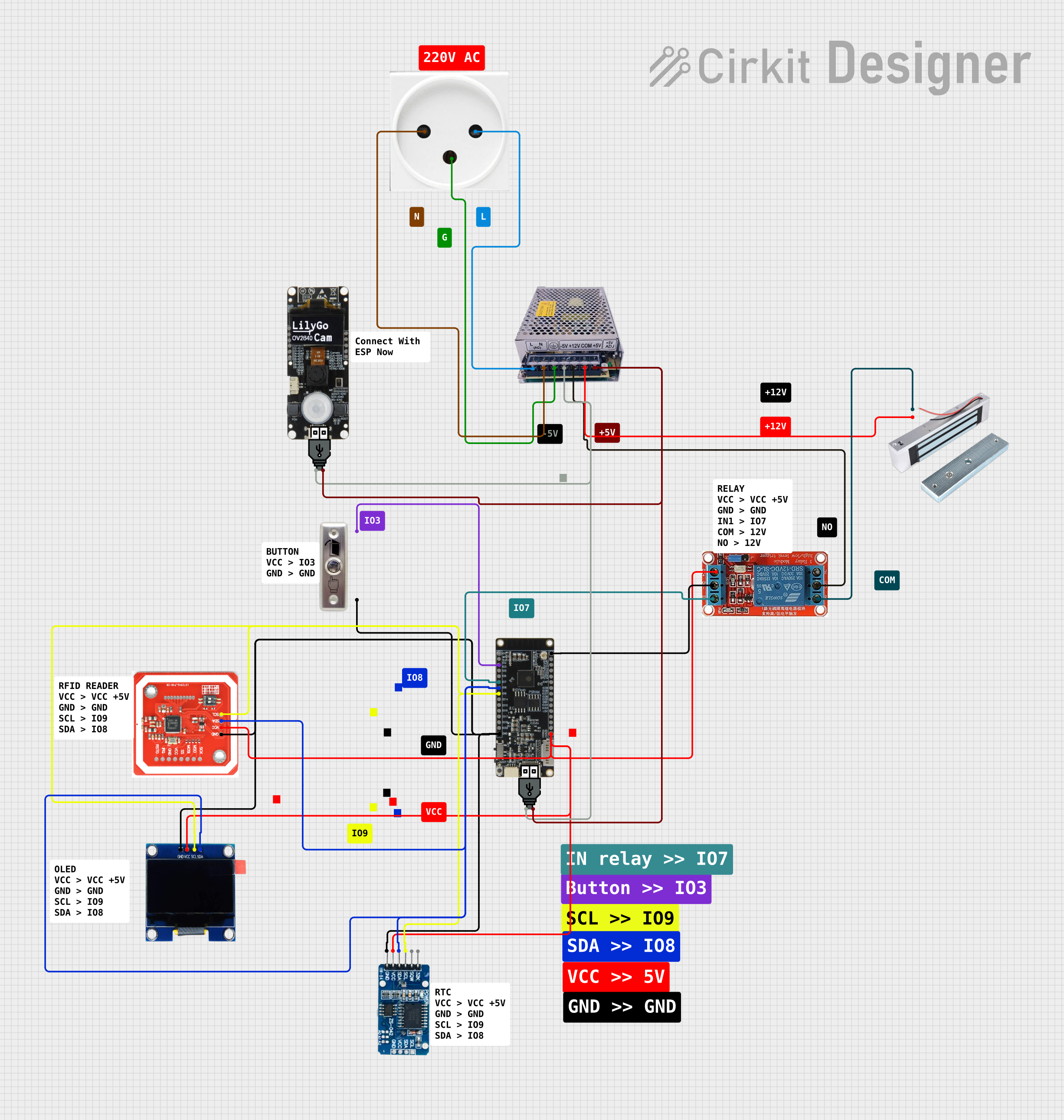
NFC-Enabled Access Control System with Real-Time Clock and OLED Display

Circuit Documentation
Summary
The circuit in question appears to be designed for access control, featuring an NFC/RFID reader for authentication, a real-time clock (RTC) for timekeeping, an OLED display for user interface, a relay to control a magnetic lock, and a microcontroller for overall management. The power supply provides both 12V and 5V outputs, which are used to power the various components. The circuit also includes a button switch that likely serves as a manual override or input device.
Component List
NFC/RFID Reader
- Description: A device used to read NFC or RFID tags for authentication purposes.
- Pins: GND, VCC, SDA, SCL
12V Relay
- Description: An electromechanical switch that allows a low-power signal to control a higher power circuit, in this case, used to control the magnetic lock.
- Pins: NO (Normally Open), COM (Common), NC (Normally Closed), IN (Input), DC- (DC Ground), DC+ (DC Power)
RTC DS3231
- Description: A real-time clock module that provides accurate timekeeping.
- Pins: 32K, SQW, SCL, SDA, VCC, GND
OLED 1.3"
- Description: A small display used for showing information to the user.
- Pins: GND, VCC, SCL, SDA
Switching Power Supply 12V 5V
- Description: A power supply unit that provides both 12V and 5V outputs.
- Pins: L (Line), N (Neutral), GND (Ground), -5V, +12V, COM (Common), +5V
Magnetic Lock
- Description: An electromagnetic locking device that is controlled by the relay.
- Pins: S (Signal), GND
Button Switch Door
- Description: A button that likely serves as a manual input for the system.
- Pins: VCC, GND
T8_S3 Microcontroller
- Description: The main controller of the circuit, interfacing with all other components.
- Pins: Multiple GPIOs, GND, 3V3, 5V
USB Power
- Description: A USB power module used to provide power to the circuit.
- Pins: + (Positive), - (Negative)
Power Outlet (IL)
- Description: A power outlet that supplies power to the switching power supply.
- Pins: N (Neutral), L (Line), GND (Ground)
Wiring Details
NFC/RFID Reader
- GND connected to system ground.
- VCC connected to 5V power supply.
- SDA connected to microcontroller SDA line.
- SCL connected to microcontroller SCL line.
12V Relay
- NO connected to the magnetic lock.
- COM connected to +12V from the power supply.
- NC not used in this circuit.
- IN connected to a GPIO on the microcontroller.
- DC- connected to system ground.
- DC+ connected to 5V power supply.
RTC DS3231
- GND connected to system ground.
- VCC connected to 5V power supply.
- SDA connected to microcontroller SDA line.
- SCL connected to microcontroller SCL line.
OLED 1.3"
- GND connected to system ground.
- VCC connected to 5V power supply.
- SDA connected to microcontroller SDA line.
- SCL connected to microcontroller SCL line.
Switching Power Supply 12V 5V
- L connected to power outlet line.
- N connected to power outlet neutral.
- GND connected to power outlet ground.
- -5V connected to USB power module negative.
- +12V connected to relay COM and magnetic lock.
- COM connected to magnetic lock ground.
- +5V connected to USB power module positive.
Magnetic Lock
- S connected to relay NO.
- GND connected to relay COM.
Button Switch Door
- VCC connected to a GPIO on the microcontroller.
- GND connected to system ground.
T8_S3 Microcontroller
- Various GPIOs connected to relay, button switch, and I2C devices (RTC, OLED, NFC/RFID reader).
- GND connected to system ground.
- 3V3 not used in this circuit.
- 5V connected to 5V power supply.
USB Power
- + connected to +5V on the power supply.
- - connected to -5V on the power supply.
Power Outlet (IL)
- N connected to power supply neutral.
- L connected to power supply line.
- GND connected to power supply ground.
Documented Code
No code was provided for the microcontroller or any other programmable components in the circuit. Therefore, this section is not applicable for the current documentation. If code becomes available, it should be documented here with appropriate comments and explanations for each function and routine.