Arduino UNO-Based Battery-Powered Gas Detection and Motor Control System
Circuit Documentation
Summary
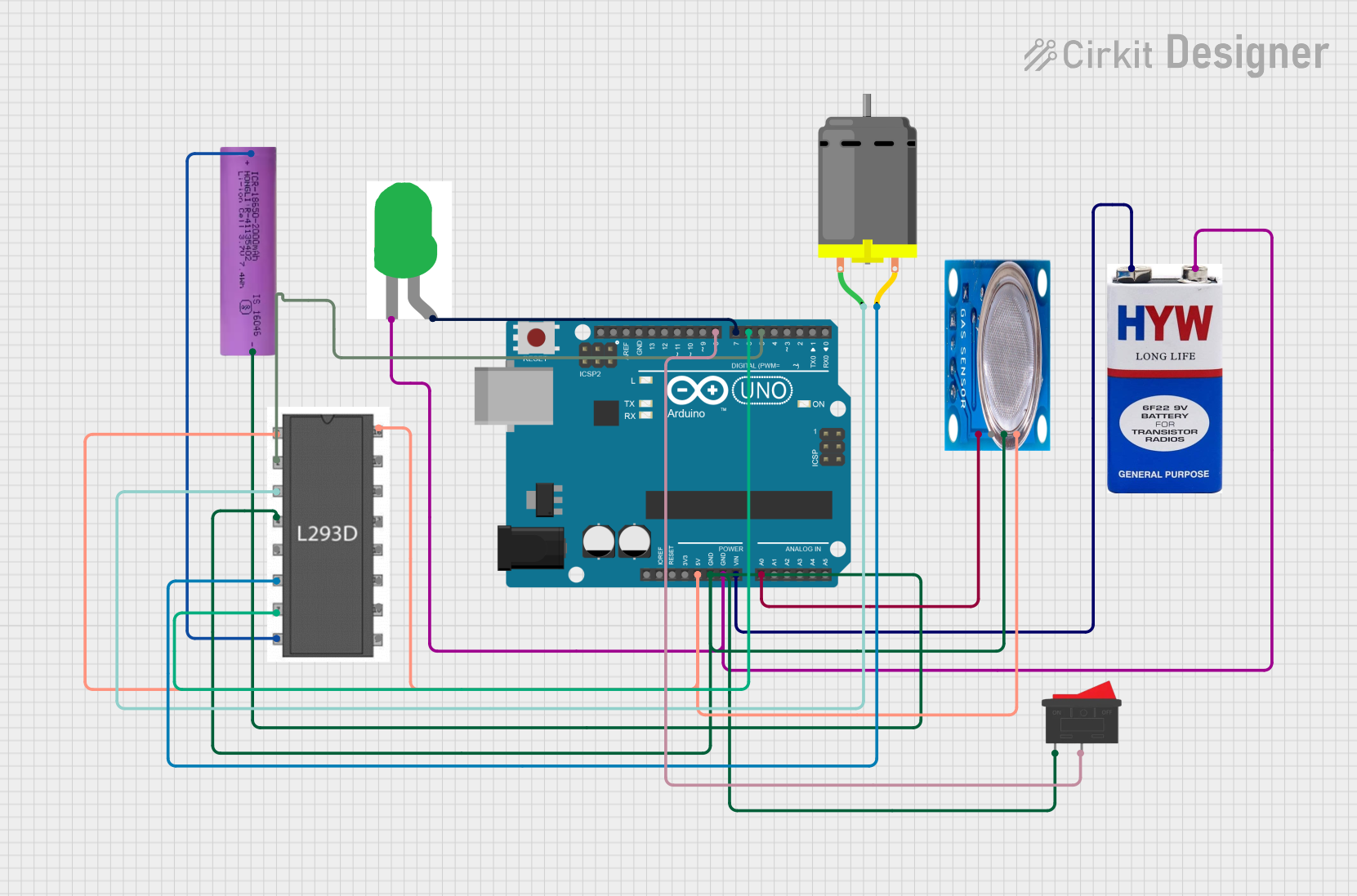
This document provides a detailed overview of a circuit that includes an Arduino UNO microcontroller, a DC motor, an L293D motor driver, an MQ-5 gas sensor, a green LED, a rocker switch, and power sources including a 9V battery and a Li-ion battery. The circuit is designed to control the DC motor and read data from the gas sensor, with visual feedback provided by the LED.
Component List
Arduino UNO
- Description: A microcontroller board based on the ATmega328P.
- Pins: UNUSED, IOREF, Reset, 3.3V, 5V, GND, Vin, A0, A1, A2, A3, A4, A5, SCL, SDA, AREF, D13, D12, D11, D10, D9, D8, D7, D6, D5, D4, D3, D2, D1, D0
Li-ion battery 18650-2000mAh 3.7V 7.4WH
- Description: A rechargeable lithium-ion battery.
- Pins: +, -
DC Motor
- Description: A motor that runs on direct current.
- Pins: pin 1, pin 2
L293D
- Description: A quadruple high-current half-H driver.
- Pins: Enable 1,2, Input 1, Output 1, GND, Output 2, Input 2, Vcc2, Vcc1, Input 4, Output 4, Output 3, Input 3, Enable 3,4
LED: Two Pin (green)
- Description: A green light-emitting diode.
- Pins: cathode, anode
MQ-5
- Description: A gas sensor for detecting LPG, natural gas, and coal gas.
- Pins: VCC, GND, Digi Out, Analog out
9V battery
- Description: A 9-volt battery.
- Pins: +, -
Rocker Switch
- Description: A switch that rocks back and forth to open or close a circuit.
- Pins: 1, 2
Wiring Details
Arduino UNO
5V connected to:
- MQ-5 (VCC)
- L293D (Enable 1,2)
- L293D (Vcc1)
GND connected to:
- Rocker Switch (pin 1)
- MQ-5 (GND)
- L293D (GND)
- Li-ion battery (negative terminal)
- LED (cathode)
- 9V battery (negative terminal)
Vin connected to:
- 9V battery (positive terminal)
D5 connected to:
- L293D (Input 1)
D6 connected to:
- L293D (Input 2)
D7 connected to:
- LED (anode)
D8 connected to:
- Rocker Switch (pin 2)
A0 connected to:
- MQ-5 (Analog out)
Li-ion battery 18650-2000mAh 3.7V 7.4WH
Positive terminal connected to:
- L293D (Vcc2)
Negative terminal connected to:
- Arduino UNO (GND)
- Rocker Switch (pin 1)
- MQ-5 (GND)
- L293D (GND)
DC Motor
pin 1 connected to:
- L293D (Output 1)
pin 2 connected to:
- L293D (Output 2)
L293D
Enable 1,2 connected to:
- Arduino UNO (5V)
Input 1 connected to:
- Arduino UNO (D5)
Output 1 connected to:
- DC Motor (pin 1)
GND connected to:
- Rocker Switch (pin 1)
- MQ-5 (GND)
- Li-ion battery (negative terminal)
- Arduino UNO (GND)
Output 2 connected to:
- DC Motor (pin 2)
Input 2 connected to:
- Arduino UNO (D6)
Vcc2 connected to:
- Li-ion battery (positive terminal)
Vcc1 connected to:
- Arduino UNO (5V)
LED: Two Pin (green)
cathode connected to:
- 9V battery (negative terminal)
- Arduino UNO (GND)
anode connected to:
- Arduino UNO (D7)
MQ-5
VCC connected to:
- Arduino UNO (5V)
GND connected to:
- Rocker Switch (pin 1)
- L293D (GND)
- Li-ion battery (negative terminal)
- Arduino UNO (GND)
Analog out connected to:
- Arduino UNO (A0)
9V battery
Positive terminal connected to:
- Arduino UNO (Vin)
Negative terminal connected to:
- LED (cathode)
- Arduino UNO (GND)
Rocker Switch
pin 1 connected to:
- MQ-5 (GND)
- L293D (GND)
- Li-ion battery (negative terminal)
- Arduino UNO (GND)
pin 2 connected to:
- Arduino UNO (D8)
Documented Code
Arduino UNO Code
void setup() {
  // put your setup code here, to run once:

}

void loop() {
  // put your main code here, to run repeatedly:

}
This code is a basic template for the Arduino UNO, with empty setup and loop functions. The setup function runs once when the microcontroller is powered on or reset, and the loop function runs continuously after the setup function has completed.