
Arduino-Based Bluetooth-Controlled Robotic Car with LED Indicators and Siren
View and Edit Project In Cirkit Designer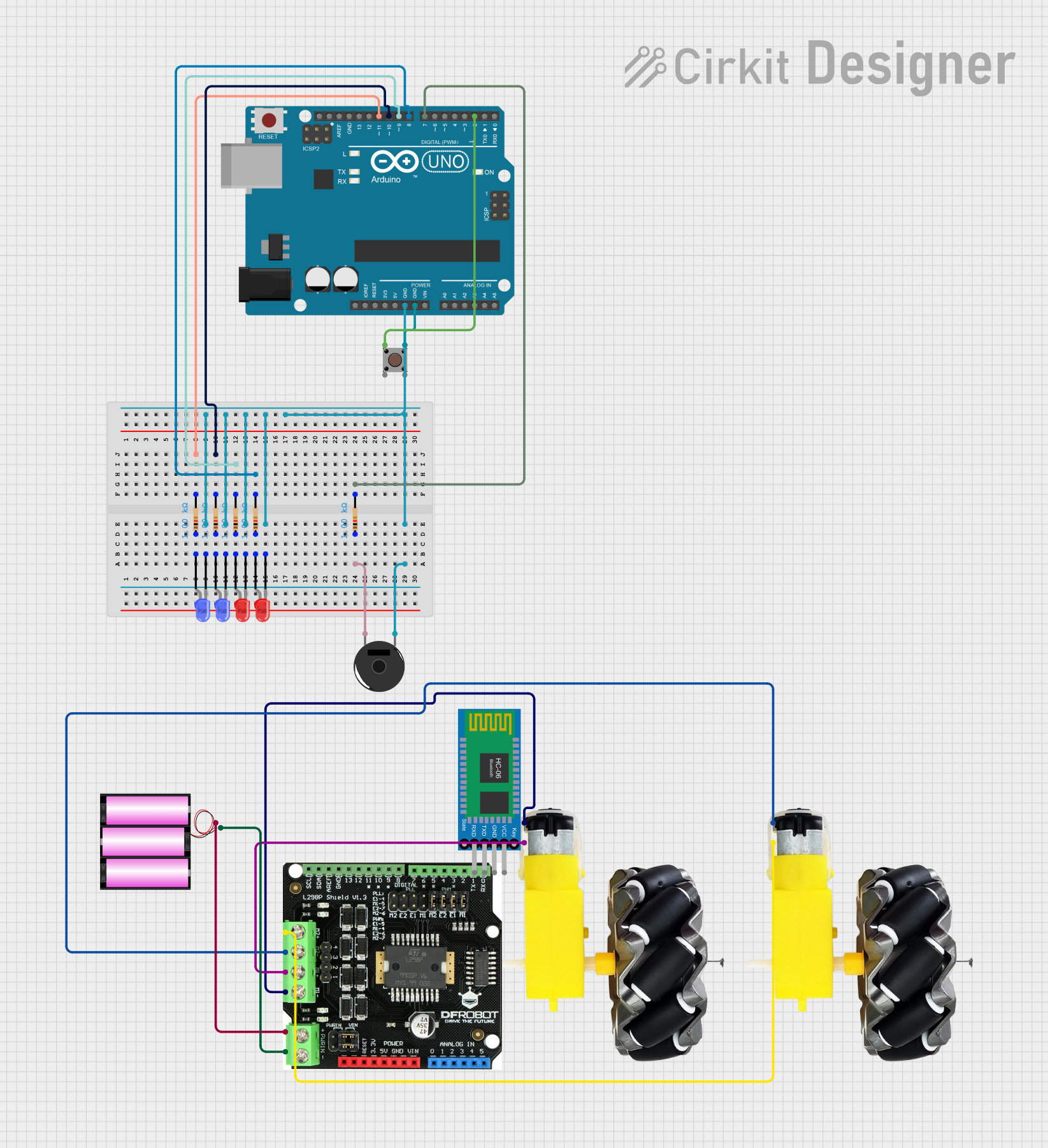
Circuit Documentation
Summary
This circuit is designed to control a motor and wheels system using an Arduino UNO and an L298P drive shield. It also includes a Bluetooth module for remote control, LEDs for visual indicators, a piezo buzzer for sound alerts, and a pushbutton for user input. The circuit is powered by a 12V battery.
Component List
Motor and Wheels
- Description: Motor and wheels assembly
- Pins: VCC, GND
L298P Drive Shield
- Description: Motor driver shield
- Pins: B-, B+, A-, A+, GND, VIN
Battery 12V
- Description: 12V power source
- Pins: +, -
Resistor
- Description: 1000 Ohms resistor
- Pins: pin1, pin2
LED: Two Pin (Red)
- Description: Red LED
- Pins: Cathode, Anode
LED: Two Pin (Blue)
- Description: Blue LED
- Pins: Cathode, Anode
Arduino UNO
- Description: Microcontroller board
- Pins: UNUSED, IOREF, Reset, 3.3V, 5V, GND, Vin, A0, A1, A2, A3, A4, A5, SCL, SDA, AREF, D13, D12, D11, D10, D9, D8, D7, D6, D5, D4, D3, D2, D1, D0
Piezo Buzzer
- Description: Sound alert device
- Pins: pin 1, pin 2
Bluetooth HC-06
- Description: Bluetooth module
- Pins: VCC, GND, TXD, RXD
Pushbutton
- Description: User input button
- Pins: Pin 3 (out), Pin 4 (out), Pin 1 (in), Pin 2 (in)
Wiring Details
Motor and Wheels
VCC connected to A+ of L298P Drive Shield
GND connected to A- of L298P Drive Shield
VCC connected to B+ of L298P Drive Shield
GND connected to B- of L298P Drive Shield
L298P Drive Shield
- B- connected to GND of Motor and Wheels
- B+ connected to VCC of Motor and Wheels
- A- connected to GND of Motor and Wheels
- A+ connected to VCC of Motor and Wheels
- GND connected to - of Battery 12V
- VIN connected to + of Battery 12V
Battery 12V
- + connected to VIN of L298P Drive Shield
- - connected to GND of L298P Drive Shield
Resistor
pin2 connected to D11 of Arduino UNO
pin1 connected to Anode of LED: Two Pin (Blue)
pin2 connected to D10 of Arduino UNO
pin1 connected to Anode of LED: Two Pin (Red)
pin2 connected to D9 of Arduino UNO
pin1 connected to Anode of LED: Two Pin (Red)
pin2 connected to D8 of Arduino UNO
pin1 connected to Anode of LED: Two Pin (Blue)
pin1 connected to pin 2 of Piezo Buzzer
pin2 connected to D7 of Arduino UNO
LED: Two Pin (Red)
Cathode connected to GND of Arduino UNO
Anode connected to pin1 of Resistor
Cathode connected to GND of Arduino UNO
Anode connected to pin1 of Resistor
LED: Two Pin (Blue)
Cathode connected to GND of Arduino UNO
Anode connected to pin1 of Resistor
Cathode connected to GND of Arduino UNO
Anode connected to pin1 of Resistor
Arduino UNO
- GND connected to Cathode of LED: Two Pin (Blue)
- GND connected to Cathode of LED: Two Pin (Red)
- GND connected to pin 1 of Piezo Buzzer
- GND connected to Pin 3 (out) of Pushbutton
- D2 connected to Pin 1 (in) of Pushbutton
- D7 connected to pin2 of Resistor
- D8 connected to pin2 of Resistor
- D9 connected to pin2 of Resistor
- D10 connected to pin2 of Resistor
- D11 connected to pin2 of Resistor
Piezo Buzzer
- pin 1 connected to GND of Arduino UNO
- pin 2 connected to pin1 of Resistor
Bluetooth HC-06
- VCC connected to 5V of Arduino UNO
- GND connected to GND of Arduino UNO
- TXD connected to D0 of Arduino UNO
- RXD connected to D1 of Arduino UNO
Pushbutton
- Pin 3 (out) connected to GND of Arduino UNO
- Pin 1 (in) connected to D2 of Arduino UNO
Code Documentation
Arduino UNO (Motor and Bluetooth Control)
//we are going to be using different variables in order to define our motor and bluetooth pins because the motor sheild is directly on top of our arudino and we cant see the pins, this makes it easier to code and debug
int E1 = 3;
int M1 = 12;
int E2 = 11;
int M2 = 13;
#define BT_RX_PIN 1
#define BT_TX_PIN 0

//we are using a char to store our incoming byte from the bluetooth module
char incomingByte;

//setup the output motor pins and also use a serial begin function in order to configure the arduino to the correct frequency for our bluetooth module to be recieving inputs
void setup() {
  pinMode(M1, OUTPUT);
  pinMode(M2, OUTPUT);
  Serial.begin(9600);
}

void loop() {
  //this means that if there is a read from the bluetooth module it will start reading those commands
  if (Serial.available() > 0) {
    //defining our incoming bytes as the read from the bluetooth module
    incomingByte = Serial.read();

    /*each of these if statements will assign 5 input commands from the bluetooth module to a specific action,
    F is forward, B is back, L is left, R is right, S is stop
    the M1 and M2 represents which direction the motors are going to be turning, high is forward, low is back,
    the E1 and E2 represents the speed control of the motors, the higher the quicker*/
    if (incomingByte == 'F') {
      digitalWrite(M1, HIGH);
      digitalWrite(M2, HIGH);
      analogWrite(E1, 100);
      analogWrite(E2, 100);

    }
    else if (incomingByte == 'B') {
      digitalWrite(M1, LOW);
      digitalWrite(M2, LOW);
      analogWrite(E1, 100);
      analogWrite(E2, 100);
    }
    else if (incomingByte == 'L') {
      digitalWrite(M1, LOW);
      digitalWrite(M2, HIGH);
      analogWrite(E1, 200);
      analogWrite(E2, 100);
    }
    else if (incomingByte == 'R') {
      digitalWrite(M1, HIGH);
      digitalWrite(M2, LOW);
      analogWrite(E1, 100);
      analogWrite(E2, 200);
    }
    else if (incomingByte == 'S') {
      analogWrite(E1, 0);
      analogWrite(E2, 0);
    }
  }
}
Arduino UNO (Lights and Sirens Control)
//This is the section of code reserved for the arduino controlling the lights and sirens

//define each pin for the 4 lights and piezo//
#define PIEZO_PIN 7
#define RED_LED_PIN_1 11
#define RED_LED_PIN