
Circuit Documentation
Summary
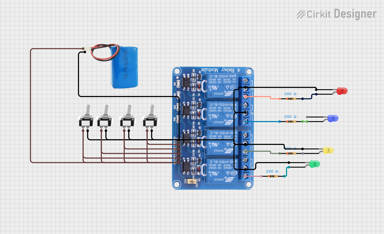
This circuit consists of a 4-channel relay module, multiple LEDs of different colors, resistors, toggle switches, and a 5V battery. The circuit is designed to control the LEDs through the relay module and toggle switches, with each LED being connected in series with a resistor to limit the current.
Component List
Relay 4 Channel 5V
- Description: A relay module with 4 channels, used to control high voltage devices with low voltage signals.
- Pins: GND, IN1, IN2, IN3, IN4, VCC, COM1, COM2, COM3, COM4, NO1, NO2, NO3, NO4, NC1, NC2, NC3, NC4
LED: Two Pin (Red)
- Description: A red LED with two pins.
- Pins: Cathode, Anode
LED: Two Pin (Yellow)
- Description: A yellow LED with two pins.
- Pins: Cathode, Anode
LED: Two Pin (Green)
- Description: A green LED with two pins.
- Pins: Cathode, Anode
LED: Two Pin (Blue)
- Description: A blue LED with two pins.
- Pins: Cathode, Anode
Resistor (200 Ohms)
- Description: A resistor with a resistance of 200 Ohms.
- Pins: Pin1, Pin2
5V Battery
- Description: A 5V battery used to power the circuit.
- Pins: Positive, Negative
Toggle Switch SPST
- Description: A single-pole single-throw (SPST) toggle switch.
- Pins: L1, COM
Wiring Details
Relay 4 Channel 5V
GND is connected to:
- Cathode of Yellow LED
- COM1, COM2, COM3, COM4 of the relay module
- COM of all Toggle Switches
- Negative of 5V Battery
- Cathode of Red LED
- Cathode of Green LED
IN1, IN2, IN3, IN4, VCC are connected to:
- L1 of all Toggle Switches
- Positive of 5V Battery
NO1 is connected to:
- Pin1 of Resistor (200 Ohms)
NO2 is connected to:
- Pin1 of Resistor (200 Ohms)
NO3 is connected to:
- Pin1 of Resistor (200 Ohms)
NO4 is connected to:
- Pin1 of Resistor (200 Ohms)
LED: Two Pin (Red)
Cathode is connected to:
- GND of Relay 4 Channel 5V
Anode is connected to:
- Pin2 of Resistor (200 Ohms)
LED: Two Pin (Yellow)
- Cathode is connected to:
- GND of Relay 4 Channel 5V
LED: Two Pin (Green)
Cathode is connected to:
- GND of Relay 4 Channel 5V
Anode is connected to:
- Pin2 of Resistor (200 Ohms)
LED: Two Pin (Blue)
- Anode is connected to:
- Pin2 of Resistor (200 Ohms)
Resistor (200 Ohms)
Pin1 is connected to:
- NO1 of Relay 4 Channel 5V
- NO2 of Relay 4 Channel 5V
- NO3 of Relay 4 Channel 5V
- NO4 of Relay 4 Channel 5V
Pin2 is connected to:
- Anode of Red LED
- Anode of Blue LED
- Anode of Green LED
5V Battery
Positive is connected to:
- IN1, IN2, IN3, IN4, VCC of Relay 4 Channel 5V
- L1 of all Toggle Switches
Negative is connected to:
- GND of Relay 4 Channel 5V
Toggle Switch SPST
L1 is connected to:
- IN1, IN2, IN3, IN4, VCC of Relay 4 Channel 5V
- Positive of 5V Battery
COM is connected to:
- GND of Relay 4 Channel 5V
Code
There is no code provided for this circuit.