Arduino UNO Controlled RGB LED and Servo System with Capacitive Sensing and HuskyLens Vision
Circuit Documentation
Summary
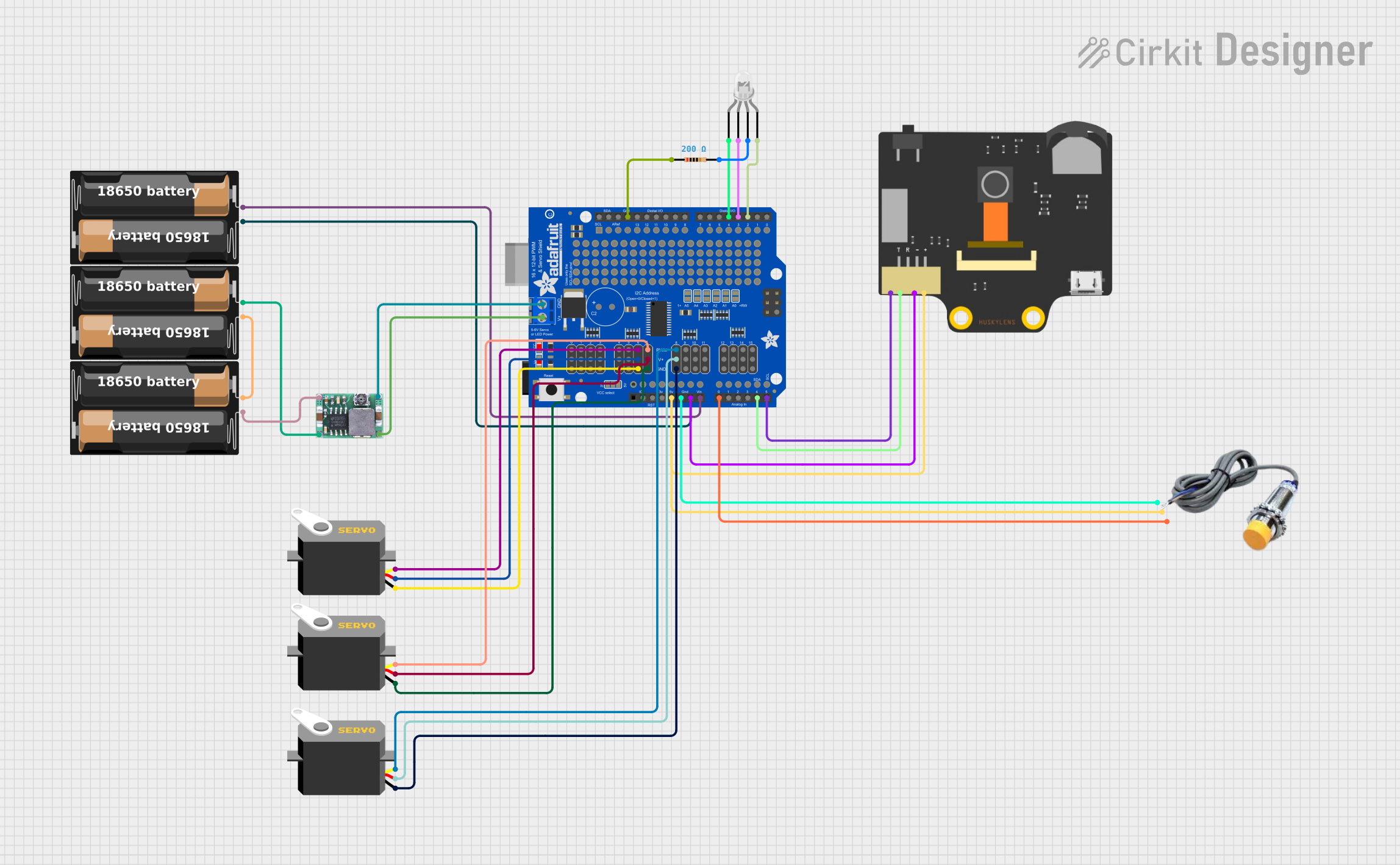
This circuit integrates various components including an Arduino UNO, multiple battery cases, a HuskyLens smart camera, an Adafruit 16-Channel PWM Servo Shield, an RGB LED, a resistor, a capacitive sensor, and several servos. The circuit is designed to interface with the HuskyLens for vision processing, utilize capacitive sensing for input, drive multiple servos via the PWM shield, and indicate status or feedback through an RGB LED. Power management is handled by battery cases and a DC-DC Step Down Buck Converter, ensuring appropriate voltage levels for the components.
Component List
Arduino UNO
- Microcontroller board based on the ATmega328P
- Provides I/O pins for interfacing with various sensors and actuators
- Operates at 5V and includes a built-in voltage regulator
Battery Cases
- Provide power to the circuit
- Each case holds batteries that supply a voltage to the connected components
HuskyLens
- An AI-powered smart camera capable of facial recognition, object tracking, and more
- Communicates with the Arduino via I2C protocol
Adafruit 16-Channel PWM Servo Shield
- Allows for the control of up to 16 servos with precise PWM signals
- Communicates with the Arduino via I2C protocol
RGB LED (Four Pin)
- Contains red, green, and blue LEDs with a common anode
- Used for status indication or user feedback
Resistor
- A 200 Ohm resistor, likely used for current limiting for the RGB LED
Capacitive Sensor
- Detects touch or proximity events
- Provides a digital signal to the Arduino
Servos
- Actuators that can be positioned with PWM signals
- Used for movement or mechanical control in the circuit
Mini-360 DC-DC Step Down Buck Converter
- Converts a higher input voltage to a lower output voltage
- Provides regulated power to components that require a specific operating voltage
Wiring Details
Arduino UNO
- 5V connected to HuskyLens VCC and Capacitive Sensor VCC
- GND connected to HuskyLens GND, Capacitive Sensor GND, and one pin of the Resistor
- A0 connected to Capacitive Sensor SIGNAL
- A4 (SCL) connected to HuskyLens SCL
- D4 connected to RGB LED red cathode
- D3 connected to RGB LED common anode
- D2 connected to RGB LED blue cathode
Battery Cases
- One battery case provides VIN to the Adafruit PWM Servo Shield
- Another battery case is connected in series with the first one and also connected to the input of the Mini-360 DC-DC Step Down Buck Converter
HuskyLens
- VCC and GND connected to Arduino 5V and GND respectively
- SCL and SDA connected to Arduino A4 and Adafruit PWM Servo Shield SCL
Adafruit 16-Channel PWM Servo Shield
- VIN and GND connected to the battery case
- 5.0V and GND connected to servos for power
- PWM6, PWM7, and PWM8 connected to servo pulse inputs
- PWRIN and GND connected to the output of the Mini-360 DC-DC Step Down Buck Converter
RGB LED
- Red cathode connected to Arduino D4
- Common anode connected to Arduino D3
- Blue cathode connected to Arduino D2
- Green cathode connected through a 200 Ohm resistor to Arduino GND
Resistor
- One pin connected to Arduino GND
- The other pin connected to RGB LED green cathode
Capacitive Sensor
- VCC and GND connected to Arduino 5V and GND respectively
- SIGNAL connected to Arduino A0
Servos
- GND connected to Adafruit PWM Servo Shield GND
- VCC connected to Adafruit PWM Servo Shield 5.0V
- Pulse inputs connected to Adafruit PWM Servo Shield PWM6, PWM7, and PWM8
Mini-360 DC-DC Step Down Buck Converter
- Input connected to the battery case
- Output connected to Adafruit PWM Servo Shield PWRIN and GND
Documented Code
Arduino UNO Code (sketch.ino)
void setup() {
  // put your setup code here, to run once:

}

void loop() {
  // put your main code here, to run repeatedly:

}
Note: The provided code for the Arduino UNO is a template with empty setup and loop functions. The actual functionality needs to be implemented based on the specific requirements of the circuit's operation.