
Li-ion Battery Management and Monitoring System with Voltage Regulation and Relay Control
View and Edit Project In Cirkit Designer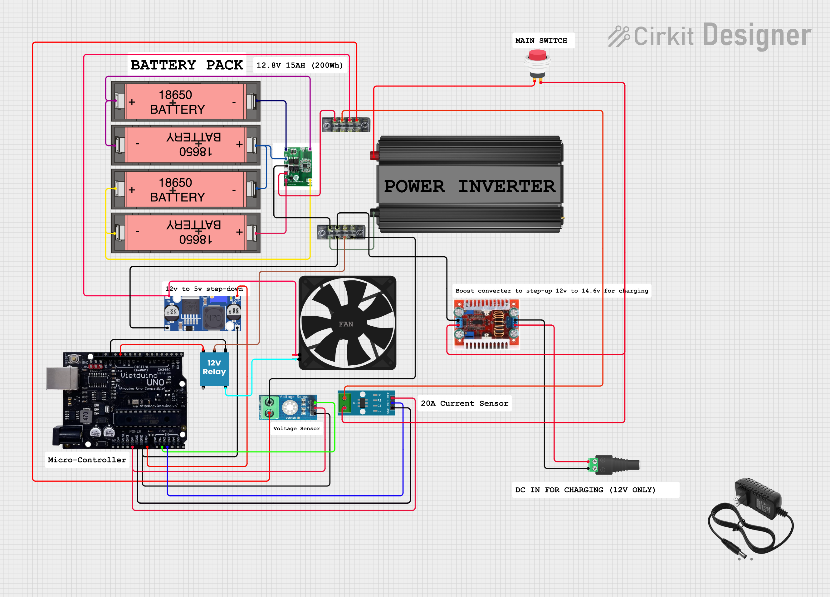
Circuit Documentation
Summary
The circuit in question appears to be a power management system utilizing multiple Li-ion 18650 batteries, a 4S-1P Lifepo4 BMS (Battery Management System), a buck converter, a power inverter, a 12V relay, a voltage sensor, terminal blocks, a Vietduino Uno microcontroller, a DC-DC step-up boost converter, a 2.1mm barrel jack with terminal block, an ACS712 current sensor, a 2Pin push switch, and a fan. The circuit is designed to manage and monitor the power from the batteries, step down and step up voltages as required, and control power to a fan based on certain conditions. The Vietduino Uno microcontroller is used to monitor and control various components in the circuit.
Component List
Li-ion 18650 Battery
- Description: Rechargeable battery used as the power source for the circuit.
Buck Converter
- Description: A DC-DC converter that steps down voltage from a higher voltage battery to a lower voltage.
Power Inverter
- Description: Converts DC power to AC power.
12V Relay
- Description: An electromechanical switch used for turning on/off a circuit path.
Voltage Sensor DC 25V
- Description: Measures the voltage in a circuit and provides feedback to the microcontroller.
Terminal Block (04-01)
- Description: A connector that allows multiple circuits to connect to each other.
Vietduino Uno USB-B
- Description: A microcontroller board based on the ATmega328, used for controlling and monitoring various components in the circuit.
DC-DC Step-Up Boost Converter
- Description: A DC-DC converter that steps up voltage from a lower voltage source to a higher voltage.
2.1mm Barrel Jack with Terminal Block
- Description: A connector for attaching external power sources to the circuit.
4S-1P Lifepo4 BMS
- Description: A battery management system for LiFePO4 batteries, ensuring safe charging and discharging.
ACS712 Current Sensor 5A 20A 30A
- Description: A hall-effect-based linear current sensor.
2Pin Push Switch
- Description: A simple push-button switch used to control the power flow in a circuit.
Fan
- Description: An electric fan powered by the circuit, likely for cooling purposes.
Comments
- Description: Placeholder for additional notes or labels within the circuit that are not physically present.
Wiring Details
Li-ion 18650 Battery
-connected to BMSB-+connected to the next battery in series or to BMSB+
Buck Converter
IN+connected to BMSP+IN-connected to BMSP-OUT+connected to Vietduino UnoVINOUT-connected to Vietduino UnoGND
Power Inverter
-connected to terminal block+connected to 2Pin Push SwitchInput +
12V Relay
+connected to Vietduino Uno12-connected to Vietduino UnoGNDCconnected to terminal blockNOconnected to FanGND
Voltage Sensor DC 25V
+connected to Vietduino Uno5V-connected to Vietduino UnoGNDoutputconnected to Vietduino UnoA1gndconnected to terminal blockvccconnected to terminal block
Terminal Block (04-01)
- Used to interconnect various components as detailed in the wiring list.
Vietduino Uno USB-B
VINconnected to Buck ConverterOUT+GNDconnected to Buck ConverterOUT-, 12V Relay-, and ACS712GND12connected to 12V Relay+A1connected to Voltage SensoroutputA2connected to ACS712OUT5Vconnected to ACS712VCCand Voltage Sensor+
DC-DC Step-Up Boost Converter
IN+connected to 2.1mm Barrel JackPOSIN-connected to 2.1mm Barrel JackNEGOUT+connected to ACS7122and 2Pin Push SwitchOutput +OUT-connected to terminal block
2.1mm Barrel Jack with Terminal Block
POSconnected to DC-DC Step-Up Boost ConverterIN+NEGconnected to DC-DC Step-Up Boost ConverterIN-
4S-1P Lifepo4 BMS
B-connected to the first battery-B1,B2,B3,B+connected to corresponding battery terminalsP+connected to terminal blockP-connected to terminal block
ACS712 Current Sensor 5A 20A 30A
1connected to terminal block2connected to DC-DC Step-Up Boost ConverterOUT+GNDconnected to Vietduino UnoGNDOUTconnected to Vietduino UnoA2VCCconnected to Vietduino Uno5V
2Pin Push Switch
Input +connected to Power Inverter+Output +connected to DC-DC Step-Up Boost ConverterOUT+
Fan
5Vconnected to Buck ConverterIN+GNDconnected to 12V RelayNO
Documented Code
No code has been provided for the microcontroller(s) in the circuit. If code is available, it should be documented here with explanations for each function and how it interacts with the hardware components.