Arduino-Controlled Temperature-Responsive Motor with PIR Motion Detection
Circuit Documentation
Summary of the Circuit
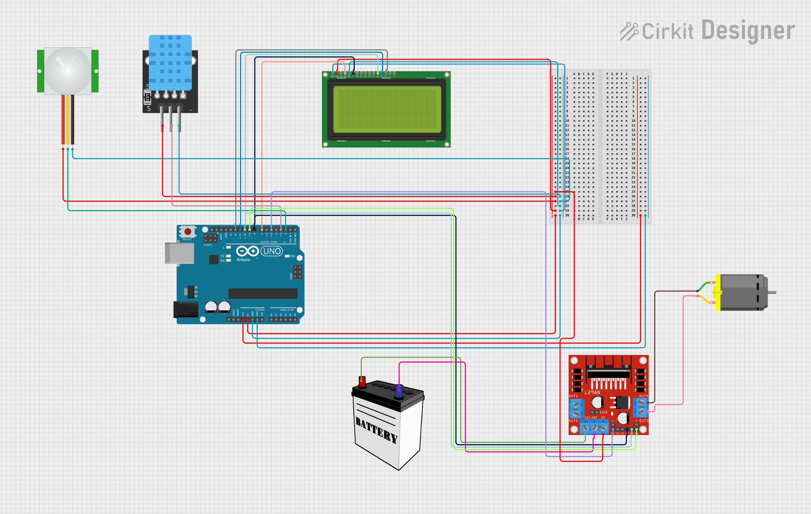
This circuit is designed to control a DC motor using input from a PIR (Passive Infrared) sensor and a temperature sensor. The motor's operation is contingent on motion detection by the PIR sensor, and its speed is modulated according to the temperature readings from the temperature sensor. The motor driver used in this circuit is the L298N module. An Arduino UNO microcontroller serves as the central processing unit, interfacing with the sensors, the motor driver, and an LCD display to provide a user interface that displays the temperature and motor status.
Component List
PIR Sensor
- Description: A sensor that detects motion by measuring changes in the infrared levels emitted by surrounding objects.
- Purpose: To detect motion and signal the Arduino to activate the motor.
Temperature Sensor (TEMP)
- Description: A sensor that measures the ambient temperature.
- Purpose: To provide temperature data to the Arduino, which uses it to adjust the motor speed.
LCD Display 20x4
- Description: A 20-character, 4-line liquid crystal display.
- Purpose: To display the temperature reading and motor status.
L298N DC Motor Driver
- Description: A module that drives DC motors by providing the necessary current and direction control.
- Purpose: To control the direction and speed of the DC motor based on commands from the Arduino.
DC Motor
- Description: An electric motor that converts electrical energy into mechanical rotation.
- Purpose: To perform a task when activated, such as moving a part of the system.
Arduino UNO
- Description: A microcontroller board based on the ATmega328P.
- Purpose: To process sensor inputs, control the motor driver, and update the LCD display.
12V Battery
- Description: A power source that provides 12 volts of DC power.
- Purpose: To supply power to the motor driver and, indirectly, to the motor.
Wiring Details
PIR Sensor
- VDD: Connected to the 5V power supply.
- SIG: Connected to digital pin D2 on the Arduino UNO.
- GND: Connected to the ground.
Temperature Sensor (TEMP)
- 5V: Connected to the 5V power supply.
- D3: Connected to digital pin D3 on the Arduino UNO.
- GND: Connected to the ground.
LCD Display 20x4
- VDD: Connected to the 5V power supply.
- RS: Connected to digital pin D7 on the Arduino UNO.
- E: Connected to digital pin D8 on the Arduino UNO.
- DB5: Connected to digital pin D10 on the Arduino UNO.
- DB6: Connected to digital pin D11 on the Arduino UNO.
- DB7: Connected to digital pin D12 on the Arduino UNO.
- RW: Connected to the ground.
- VSS: Connected to the ground.
L298N DC Motor Driver
- 12V: Connected to the VCC of the 12V battery.
- GND: Connected to the GND of the 12V battery.
- 5V: Connected to the 5V power supply.
- ENA: Connected to digital pin D5 on the Arduino UNO.
- IN3: Connected to digital pin D8 on the Arduino UNO.
- IN4: Connected to digital pin D10 on the Arduino UNO.
- ENB: Connected to digital pin D9 on the Arduino UNO.
- OUT3: Connected to pin 2 of the DC Motor.
- OUT4: Connected to pin 1 of the DC Motor.
DC Motor
- Pin 1: Connected to OUT4 on the L298N DC motor driver.
- Pin 2: Connected to OUT3 on the L298N DC motor driver.
Documented Code
/*
 * This Arduino sketch controls a DC motor using a PIR sensor and a temperature sensor.
 * The motor turns on when motion is detected by the PIR sensor and its speed is
 * adjusted based on the temperature readings from the temperature sensor.
 * The motor driver is controlled via the L298N module.
 */

#include <LiquidCrystal.h>

// Pin definitions
const int pirPin = 2; // PIR sensor signal pin
const int tempPin = 3; // Temperature sensor signal pin
const int enaPin = 5; // Motor driver ENA pin
const int enbPin = 9; // Motor driver ENB pin
const int in3Pin = 8; // Motor driver IN3 pin
const int in4Pin = 10; // Motor driver IN4 pin
const int rsPin = 7; // LCD RS pin
const int ePin = 8; // LCD E pin
const int db5Pin = 10; // LCD DB5 pin
const int db6Pin = 11; // LCD DB6 pin
const int db7Pin = 12; // LCD DB7 pin

// Initialize the LCD
LiquidCrystal lcd(rsPin, ePin, db5Pin, db6Pin, db7Pin);

void setup() {
  // Initialize serial communication
  Serial.begin(9600);

  // Initialize pins
  pinMode(pirPin, INPUT);
  pinMode(tempPin, INPUT);
  pinMode(enaPin, OUTPUT);
  pinMode(enbPin, OUTPUT);
  pinMode(in3Pin, OUTPUT);
  pinMode(in4Pin, OUTPUT);

  // Initialize LCD
  lcd.begin(20, 4);
  lcd.print("Motor Control System");
}

void loop() {
  // Read PIR sensor
  int pirState = digitalRead(pirPin);

  // Read temperature sensor (assuming analog input)
  int tempValue = analogRead(tempPin);
  int motorSpeed = map(tempValue, 0, 1023, 0, 255);

  // Display temperature on LCD
  lcd.setCursor(0, 1);
  lcd.print("Temp: ");
  lcd.print(tempValue);

  if (pirState == HIGH) {
    // Motion detected, turn on motor
    digitalWrite(in3Pin, HIGH);
    digitalWrite(in4Pin, LOW);
    analogWrite(enaPin, motorSpeed);
    analogWrite(enbPin, motorSpeed);
    lcd.setCursor(0, 2);
    lcd.print("Motor: ON ");
  } else {
    // No motion, turn off motor
    digitalWrite(in3Pin, LOW);
    digitalWrite(in4Pin, LOW);
    analogWrite(enaPin, 0);
    analogWrite(enbPin, 0);
    lcd.setCursor(0, 2);
    lcd.print("Motor: OFF");
  }

  delay(1000); // Delay for stability
}
This code is responsible for reading the PIR sensor to detect motion and the temperature sensor to determine the ambient temperature. It then controls the motor's operation and speed based on these readings and displays the status on the LCD screen.