74HC00 NAND Gate-Based LED Driver Circuit
Circuit Documentation
Summary of the Circuit
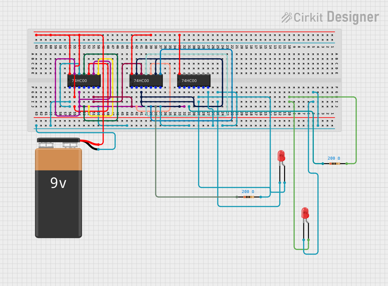
This circuit appears to be a logic circuit utilizing three 74HC00 quad 2-input NAND gate ICs. It also includes two LEDs, each with a current-limiting resistor, and a 9V battery as the power source. The 74HC00 ICs are interconnected in a manner that suggests a complex logic function is being implemented. The LEDs are likely used as indicators, possibly to display the output of the logic gates. The circuit does not include any microcontroller code, as the input code list is empty.
Component List
74HC00 Quad 2-Input NAND Gate IC
- Description: A quad 2-input NAND gate IC that contains four independent gates each of which performs the logic NAND function.
- Pins: 1A, 1B, 1Y, 2A, 2B, 2Y, GND, 3Y, 3A, 3B, 4Y, 4A, 4B, VCC
Resistor (200 Ohms)
- Description: A resistor with a resistance value of 200 Ohms, used to limit current through the LEDs.
- Pins: pin1, pin2
LED: Two Pin (red)
- Description: A standard red LED with an anode and cathode for indicating power or logic states.
- Pins: cathode, anode
9V Battery
- Description: A standard 9V battery used as the power source for the circuit.
- Pins: -, +
Wiring Details
74HC00 Quad 2-Input NAND Gate IC
- GND: Connected to the cathodes of both LEDs and the negative terminal of the 9V battery.
- VCC: Connected to the positive terminal of the 9V battery.
- 1A, 4A: Connected together and to the GND net.
- 1B, 4B, 3A: Connected together.
- 1Y: Connected to the anode of one LED through a 200 Ohm resistor.
- 2A, 4Y: Connected together.
- 2B, 3Y: Connected together.
- 2Y: Connected to the anode of the other LED through a 200 Ohm resistor.
Resistor (200 Ohms)
- pin1: Connected to the 1Y pin of one 74HC00 IC and the anode of one LED.
- pin2: Connected to the 2Y pin of another 74HC00 IC and the anode of the other LED.
LED: Two Pin (red)
- cathode: Connected to the GND net.
- anode: Connected to the respective 200 Ohm resistor.
9V Battery
- -: Connected to the GND net.
- +: Connected to the VCC net of all 74HC00 ICs.
Documented Code
There is no microcontroller code provided for this circuit. Therefore, this section is not applicable.
Please note that the above documentation is based on the provided parts list and electrical net list. The actual functionality of the circuit would require further analysis of the logic implemented by the interconnections of the 74HC00 ICs.