Cirkit Designer
Your all-in-one circuit design IDE
Home /
Project Documentation
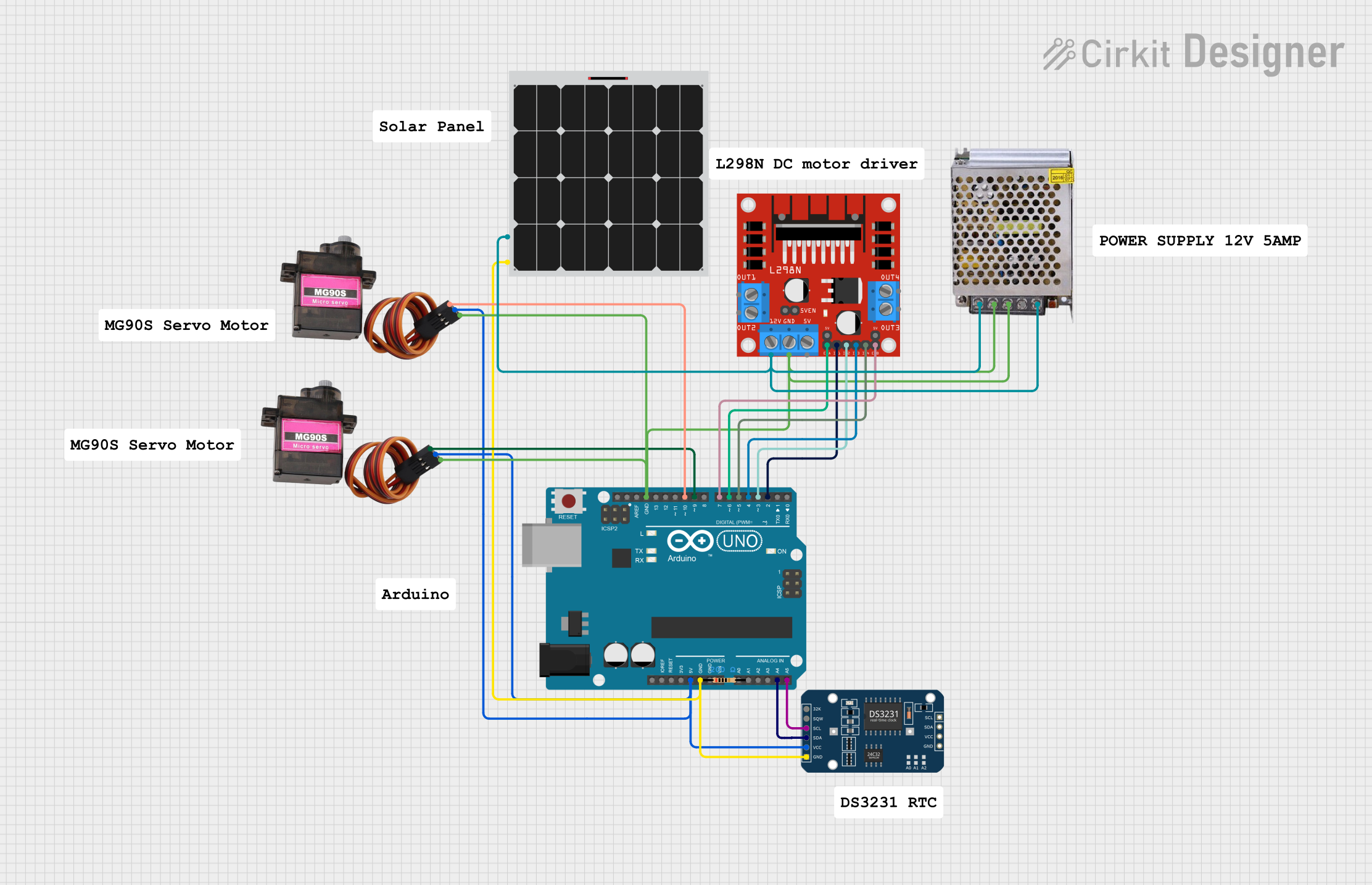
Arduino UNO Solar-Powered Robotic Arm with Real-Time Clock
Circuit Documentation
Summary
This document provides a detailed overview of a circuit that includes an Arduino UNO microcontroller, two MG90S servos, a DS3231 RTC module, a solar panel, an L298N DC motor driver, resistors, and a 12V power supply. The circuit is designed to control servos and a DC motor, and it includes a real-time clock for time-based operations. The Arduino UNO serves as the central controller, interfacing with the other components.
Component List
Arduino UNO
- Description: A microcontroller board based on the ATmega328P.
- Pins: UNUSED, IOREF, Reset, 3.3V, 5V, GND, Vin, A0, A1, A2, A3, A4, A5, SCL, SDA, AREF, D13, D12, D11, D10, D9, D8, D7, D6, D5, D4, D3, D2, D1, D0
MG90S Servo (x2)
- Description: A micro servo motor.
- Pins: SIG, VCC, GND
DS3231 RTC
- Description: A real-time clock module.
- Pins: 32K, SQW, SCL, SDA, VCC, GND
Solar Panel
- Description: A solar panel for generating electrical power.
- Pins: +, -
L298N DC Motor Driver
- Description: A dual H-Bridge motor driver.
- Pins: OUT1, OUT2, 12V, GND, 5V, OUT3, OUT4, 5V-ENA-JMP-I, 5V-ENA-JMP-O, +5V-J1, +5V-J2, ENA, IN1, IN2, IN3, IN4, ENB
Resistor (x2)
- Description: A resistor with a resistance of 200 Ohms.
- Pins: pin1, pin2
POWER SUPPLY 12V 5AMP
- Description: A power supply providing 12V DC at 5A.
- Pins: 220V Positive Pole (AC), 220V Negative Pole (AC), GND, GND (DC), 12V-24V Output (DC)
Wiring Details
Arduino UNO
- 5V connected to VCC of both MG90S servos and VCC of DS3231 RTC.
- GND connected to GND of both MG90S servos, GND of DS3231 RTC, GND of L298N DC motor driver, and - of Solar Panel.
- A4 connected to SDA of DS3231 RTC.
- A5 connected to SCL of DS3231 RTC.
- D10 connected to SIG of one MG90S servo.
- D9 connected to SIG of the other MG90S servo.
- D7 connected to ENB of L298N DC motor driver.
- D6 connected to ENA of L298N DC motor driver.
- D5 connected to IN4 of L298N DC motor driver.
- D4 connected to IN3 of L298N DC motor driver.
- D3 connected to IN2 of L298N DC motor driver.
- D2 connected to IN1 of L298N DC motor driver.
MG90S Servo (1)
- VCC connected to 5V of Arduino UNO.
- GND connected to GND of Arduino UNO.
- SIG connected to D10 of Arduino UNO.
MG90S Servo (2)
- VCC connected to 5V of Arduino UNO.
- GND connected to GND of Arduino UNO.
- SIG connected to D9 of Arduino UNO.
DS3231 RTC
- VCC connected to 5V of Arduino UNO.
- GND connected to GND of Arduino UNO.
- SDA connected to A4 of Arduino UNO.
- SCL connected to A5 of Arduino UNO.
Solar Panel
- + connected to 12V of L298N DC motor driver.
- - connected to GND of Arduino UNO.
L298N DC Motor Driver
- GND connected to GND of Arduino UNO.
- 12V connected to + of Solar Panel.
- ENB connected to D7 of Arduino UNO.
- ENA connected to D6 of Arduino UNO.
- IN4 connected to D5 of Arduino UNO.
- IN3 connected to D4 of Arduino UNO.
- IN2 connected to D3 of Arduino UNO.
- IN1 connected to D2 of Arduino UNO.
POWER SUPPLY 12V 5AMP
- 220V Positive Pole (AC) connected to 12V of L298N DC motor driver.
- 220V Negative Pole (AC) connected to GND of L298N DC motor driver.
- GND connected to GND of L298N DC motor driver.
- 12V-24V Output (DC) connected to 12V of L298N DC motor driver.
Documented Code
Arduino UNO Code
void setup() {
  // put your setup code here, to run once:

}

void loop() {
  // put your main code here, to run repeatedly:

}
This code is a basic template for the Arduino UNO. The setup() function is used to initialize any settings or configurations, and the loop() function contains the main code that runs repeatedly.