
Arduino Nano-Controlled Environment-Responsive Robotics System
View and Edit Project In Cirkit Designer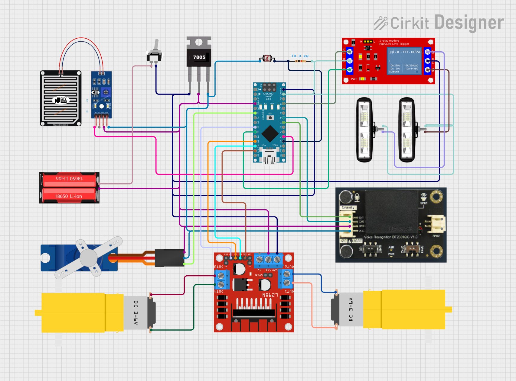
Circuit Documentation
Summary
This circuit is designed to interface various sensors, actuators, and a microcontroller to perform a set of tasks that likely involve environmental sensing, data processing, and actuation based on sensor inputs. The core of the circuit is an Arduino Nano, which controls a servo motor, a relay module, a motor driver for two DC motors, and interfaces with a rain sensor, a voice recognition module, and a photocell (LDR). A 7805 voltage regulator is used to provide a stable 5V supply to the components from a 18650 Li-Ion battery, and a toggle switch is included to control power to the circuit.
Component List
- Photocell (LDR): A light-sensitive resistor that changes its resistance based on the light intensity.
- 1 Channel 5V Relay Module: An electrically operated switch that allows the Arduino to control higher power devices.
- Motor Amarillo Motorreductor Hobby: A DC motor with a gearbox for increased torque.
- Arduino Nano: A small, complete, and breadboard-friendly microcontroller board based on the ATmega328P.
- 18650 Li-Ion Battery: A rechargeable battery providing the power source for the circuit.
- Tower Pro SG90 Servo: A small and lightweight servo motor capable of precise control.
- Resistor (10k Ohms): A passive component used to create resistance in the flow of electric current.
- RAIN SENSOR: A sensor that detects the presence of water or rain.
- DF ROBOT GRAVITY VOICE RECOGNITION MODULE: A module that can recognize voice commands.
- L298N DC Motor Driver: A driver module capable of controlling two DC motors with direction and speed control.
- Front Light: A light source, possibly for illumination or indication.
- 7805 Voltage Regulator: A component that converts a higher input voltage into a stable 5V output voltage.
- Toggle Switch SPST: A single-pole single-throw switch used to control the power supply to the circuit.
Wiring Details
Photocell (LDR)
- pin 0: Connected to 5V supply.
- pin 1: Connected to one end of a 10k Ohm resistor, other end to GND, and to Arduino Nano A0 for analog input.
1 Channel 5V Relay Module
- VCC+: Connected to Arduino Nano 5V.
- VCC- (GND): Connected to GND.
- IN: Controlled by Arduino Nano D7.
- N.O.: Connected to the positive side of a front light.
- COM: Connected to the positive voltage supply through a toggle switch.
- N.C.: Connected to the positive side of another front light.
Motor Amarillo Motorreductor Hobby (Two Instances)
- vcc: Connected to L298N DC motor driver OUT2 and OUT4 respectively.
- GND: Connected to L298N DC motor driver OUT1 and OUT3 respectively.
Arduino Nano
- D1/TX, D0/RX, RESET, D2, D4, D5, D8, D12/MISO, A7, A6, A2, A3, AREF, 3V3, D13/SCK: Not connected.
- GND: Common ground for the circuit.
- D3: Connected to Tower Pro SG90 servo Signal.
- D6, D9, D10, D11/MOSI: Control signals for L298N DC motor driver.
- VIN: Connected to 7805 Voltage Regulator output and Toggle Switch SPST COM.
- 5V: Supplies power to the 1 Channel 5V Relay Module VCC+.
- A0: Receives analog input from Photocell (LDR) through a 10k Ohm resistor.
- A1: Receives analog input from RAIN SENSOR AO.
- A4, A5: Connected to DF ROBOT GRAVITY VOICE RECOGNITION MODULE D/T and C/R respectively.
18650 Li-Ion Battery
- Positive: Connected to Toggle Switch SPST L1.
- Negative: Common ground for the circuit.
Tower Pro SG90 Servo
- Signal: Controlled by Arduino Nano D3.
- +5V: Connected to 5V supply.
- GND: Common ground for the circuit.
Resistor (10k Ohms)
- pin1: Connected to Photocell (LDR) pin 1.
- pin2: Connected to GND.
RAIN SENSOR
- AO: Connected to Arduino Nano A1.
- DO: Not connected.
- GRD: Common ground for the circuit.
- VCC: Connected to 5V supply.
DF ROBOT GRAVITY VOICE RECOGNITION MODULE
- D/T: Connected to Arduino Nano A4.
- C/R: Connected to Arduino Nano A5.
- GND: Common ground for the circuit.
- VCC: Connected to 5V supply.
- -: Not connected.
- +: Not connected.
L298N DC Motor Driver
- OUT1, OUT2, OUT3, OUT4: Connected to the two Motor Amarillo Motorreductor Hobby instances.
- 12V: Connected to the positive voltage supply through a toggle switch.
- GND: Common ground for the circuit.
- 5V: Not connected.
- 5V-ENA-JMP-I, 5V-ENA-JMP-O, +5V-J1, +5V-J2, ENA, ENB: Not connected.
- IN1, IN2, IN3, IN4: Controlled by Arduino Nano D11/MOSI, D10, D9, D6 respectively.
Front Light (Two Instances)
- POSITIF: One connected to 1 Channel 5V Relay Module N.O., the other to N.C.
- NEGATIF: Common ground for the circuit.
7805 Voltage Regulator
- Vin: Connected to the positive voltage supply through a toggle switch.
- Gnd: Common ground for the circuit.
- Vout: Connected to 5V supply for the circuit.
Toggle Switch SPST
- L1: Connected to 18650 Li-Ion Battery Positive.
- COM: Connected to 7805 Voltage Regulator Vin, Arduino Nano VIN, and L298N DC motor driver 12V.
Documented Code
Arduino Nano (Instance ID: 9eeb13a1-4dae-44cc-aaea-7695383bdaac)
sketch.ino
void setup() {
  // put your setup code here, to run once:

}

void loop() {
  // put your main code here, to run repeatedly:

}
documentation.txt
(No additional documentation provided for the code)
(Note: The provided code is a template with no specific functionality. It needs to be filled in with the logic to control the circuit based on the requirements of the project.)