Raspberry Pi Zero W-Based Security System with PIR, Ultrasonic Sensors, and Camera
Circuit Documentation
Summary
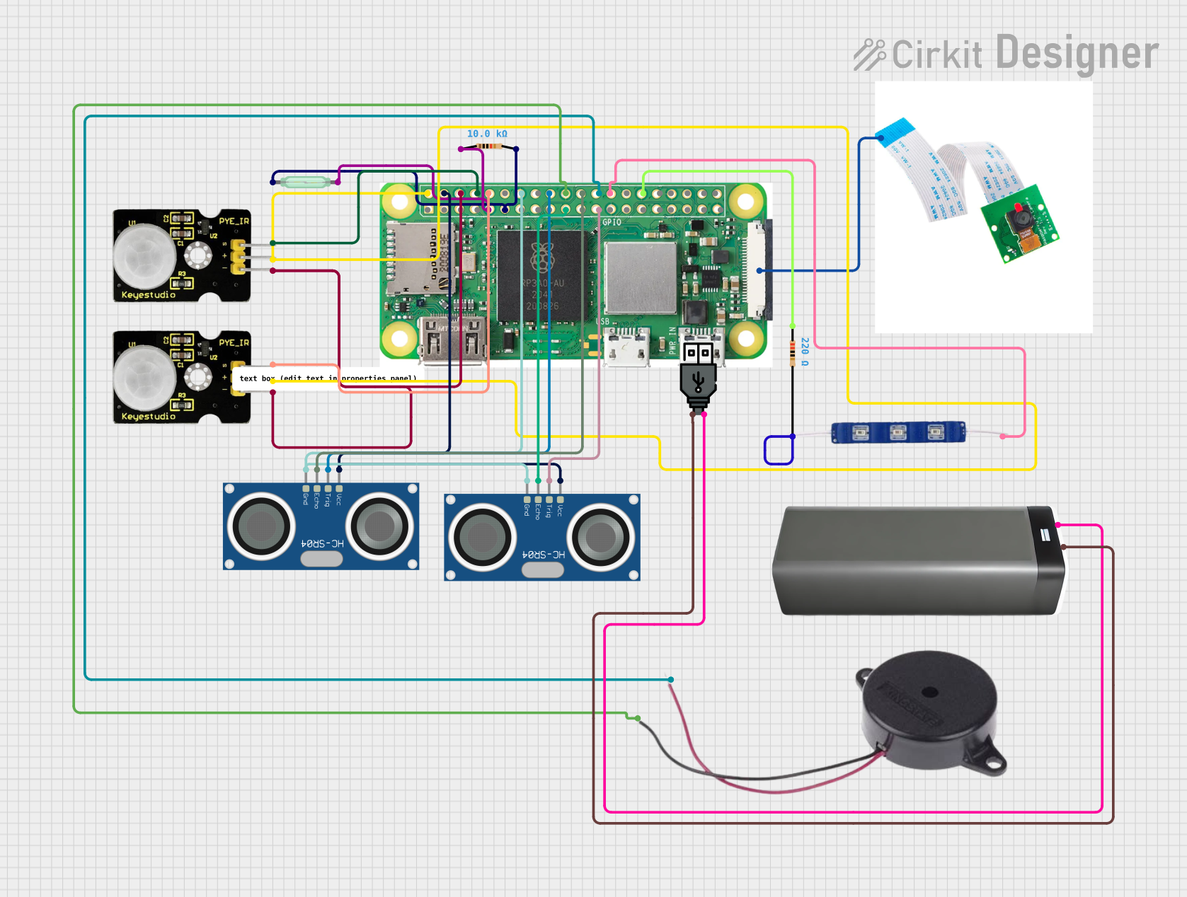
This circuit integrates various sensors and actuators with a Raspberry Pi Zero W to create a multifunctional system. The Raspberry Pi Zero W serves as the central processing unit, interfacing with PIR sensors for motion detection, HC-SR04 ultrasonic sensors for distance measurement, a reed switch for magnetic field detection, a buzzer for audio signaling, and a 12V blue LED for visual indication. The circuit is powered through a USB power source connected to a battery pack, ensuring portable power supply. The Raspberry Pi Camera is also connected for image capture capabilities.
Component List
Raspberry Pi Zero W
- A low-cost, compact variant of the Raspberry Pi with wireless LAN and Bluetooth connectivity.
- Pins: 5V, 3V3, multiple GPIOs, GND, CSI for camera connection.
Resistor (10k Ohms)
- A passive two-terminal electrical component that implements electrical resistance as a circuit element.
Resistor (220 Ohms)
- A passive two-terminal electrical component that implements electrical resistance as a circuit element.
Reed Switch
- An electrical switch operated by an applied magnetic field.
Raspberry Pi Camera
- A camera module designed specifically for Raspberry Pi boards.
HC-SR04 Ultrasonic Sensor (x2)
- An ultrasonic ranging module that provides 2cm to 400cm non-contact measurement functionality.
PIR Sensor (x2)
- A passive infrared sensor that measures infrared (IR) light radiating from objects in its field of view.
Buzzer
- An audio signaling device that can be used to create beeps, tones, and alerts.
USB Power
- A power source that provides power through a USB connection.
Battery Pack
- A portable power source that can be used to power the circuit.
12V Blue LED
- A light-emitting diode that emits blue light when powered.
Wiring Details
Raspberry Pi Zero W
- 5V connected to PIR Sensors (VCC), HC-SR04 Ultrasonic Sensors (VCC).
- GROUND connected to PIR Sensors (GND), HC-SR04 Ultrasonic Sensors (GND), Buzzer (NEGATIVE), Resistor (10k Ohms, pin1), Resistor (220 Ohms, pin1).
- GPIO 14 connected to PIR Sensor (Data).
- GPIO 15 connected to PIR Sensor (Data).
- GPIO 24 connected to HC-SR04 Ultrasonic Sensor (TRIG).
- GPIO 25 connected to HC-SR04 Ultrasonic Sensor (ECHO).
- GPIO 8 connected to Buzzer (POSITIVE).
- GPIO 7 connected to 12V Blue LED (VCC).
- GPIO 17 connected to Reed Switch (pin 1) through Resistor (10k Ohms).
- GPIO 10 connected to HC-SR04 Ultrasonic Sensor (ECHO).
- GPIO 11 connected to HC-SR04 Ultrasonic Sensor (TRIG).
- CSI (CAMERA) connected to Raspberry Pi Camera.
Resistor (10k Ohms)
- One pin connected to GROUND.
- Other pin connected to Reed Switch (pin 2) and Raspberry Pi Zero W (GPIO 17).
Resistor (220 Ohms)
- One pin connected to GROUND.
- Other pin connected to 12V Blue LED (GND).
Reed Switch
- One pin connected to Resistor (10k Ohms) and Raspberry Pi Zero W (GPIO 17).
- Other pin connected to Resistor (10k Ohms).
PIR Sensors
- VCC pins connected to Raspberry Pi Zero W (5V).
- GND pins connected to Raspberry Pi Zero W (GROUND).
- Data pins connected to Raspberry Pi Zero W (GPIO 14 and GPIO 15).
HC-SR04 Ultrasonic Sensors
- VCC pins connected to Raspberry Pi Zero W (5V).
- GND pins connected to Raspberry Pi Zero W (GND).
- TRIG pins connected to Raspberry Pi Zero W (GPIO 24 and GPIO 11).
- ECHO pins connected to Raspberry Pi Zero W (GPIO 25 and GPIO 10).
Buzzer
- POSITIVE pin connected to Raspberry Pi Zero W (GPIO 8).
- NEGATIVE pin connected to Raspberry Pi Zero W (GND).
12V Blue LED
- VCC pin connected to Raspberry Pi Zero W (GPIO 7).
- GND pin connected to Resistor (220 Ohms).
Power Connections
- USB Power "+" and Battery Pack "+" connected together.
- USB Power "-" and Battery Pack "-" connected together.
Documented Code
No code has been provided for the microcontrollers in the circuit. The documentation of the code would typically include descriptions of the functionality implemented by the code, such as reading sensor data, controlling actuators, and communicating with external devices. It would also include the actual source code, properly commented to explain the logic and flow of the program. Since no code is available, this section remains empty.