
Circuit Documentation
Summary
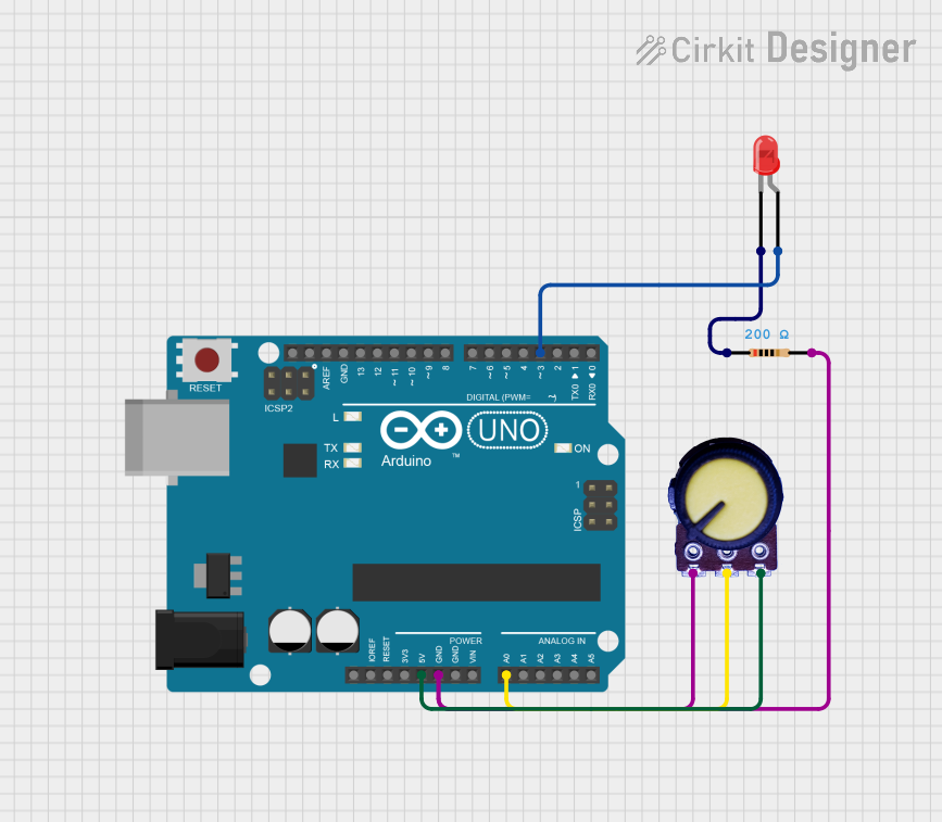
This circuit involves an Arduino UNO, a potentiometer, a red LED, and a resistor. The potentiometer is used to control the brightness of the LED through Pulse Width Modulation (PWM) using the Arduino UNO. The potentiometer's output is read by the Arduino, which then adjusts the LED's brightness accordingly.
Component List
LED: Two Pin (red)
- Description: A red LED with two pins: anode and cathode.
- Pins: cathode, anode
Potentiometer
- Description: A variable resistor with three pins: GND, Output, and VCC.
- Pins: GND, Output, VCC
Arduino UNO
- Description: A microcontroller board based on the ATmega328P.
- Pins: UNUSED, IOREF, Reset, 3.3V, 5V, GND, Vin, A0, A1, A2, A3, A4, A5, SCL, SDA, AREF, D13, D12, D11, D10, D9, D8, D7, D6, D5, D4, D3, D2, D1, D0
Resistor
- Description: A resistor with a resistance of 200 Ohms.
- Pins: pin1, pin2
- Properties:
- Resistance: 200 Ohms
Wiring Details
LED: Two Pin (red)
- anode connected to Arduino UNO D3
- cathode connected to Resistor pin1
Potentiometer
- VCC connected to Arduino UNO 5V
- GND connected to Resistor pin2 and Arduino UNO GND
- Output connected to Arduino UNO A0
Arduino UNO
- 5V connected to Potentiometer VCC
- GND connected to Potentiometer GND and Resistor pin2
- A0 connected to Potentiometer Output
- D3 connected to LED anode
Resistor
- pin1 connected to LED cathode
- pin2 connected to Potentiometer GND and Arduino UNO GND
Code Documentation
Arduino UNO Code
/*
 * This Arduino Sketch reads the value from a potentiometer connected to A0
 * and uses it to control the brightness of an LED connected to pin D3 using PWM.
 */

const int potPin = A0; // Pin where the potentiometer is connected
const int ledPin = 3;  // Pin where the LED is connected

void setup() {
  pinMode(ledPin, OUTPUT); // Set the LED pin as an output
}

void loop() {
  int potValue = analogRead(potPin); // Read the potentiometer value
  int ledValue = map(potValue, 0, 1023, 0, 255); // Map to PWM range
  analogWrite(ledPin, ledValue); // Set the LED brightness
  delay(10); // Small delay for stability
}
Potentiometer Code
/*
 * This Arduino Sketch reads the value from a potentiometer connected to A0
 * and sends the value over serial communication to control the brightness of
 * an LED connected to another microcontroller.
 */

const int potPin = A0; // Pin where the potentiometer is connected

void setup() {
  Serial.begin(9600); // Initialize serial communication at 9600 baud
}

void loop() {
  int potValue = analogRead(potPin); // Read the potentiometer value
  Serial.println(potValue); // Send the potentiometer value over serial
  delay(10); // Small delay for stability
}
LED Control Code
/*
 * This Arduino Sketch receives a potentiometer value over serial communication
 * and uses it to control the brightness of an LED connected to pin D3 using PWM.
 */

const int ledPin = 3;  // Pin where the LED is connected

void setup() {
  pinMode(ledPin, OUTPUT); // Set the LED pin as an output
  Serial.begin(9600); // Initialize serial communication at 9600 baud
}

void loop() {
  if (Serial.available() > 0) { // Check if data is available to read
    int potValue = Serial.parseInt(); // Read the potentiometer value
    int ledValue = map(potValue, 0, 1023, 0, 255); // Map to PWM range
    analogWrite(ledPin, ledValue); // Set the LED brightness
  }
  delay(10); // Small delay for stability
}
Placeholder Code
/*
 * This Arduino Sketch is a placeholder for the microcontroller with instance
 * ID: 2e79077f-6d16-40ef-b6c7-002e7c6762c3. Currently, this microcontroller
 * is not connected to any components in the circuit. This code can be
 * expanded in the future to include specific functionalities as needed.
 */

void setup() {
  // put your setup code here, to run once:
}

void loop() {
  // put your main code here, to run repeatedly:
}
This documentation provides a comprehensive overview of the circuit, including the components used, their wiring details, and the code running on the microcontrollers.