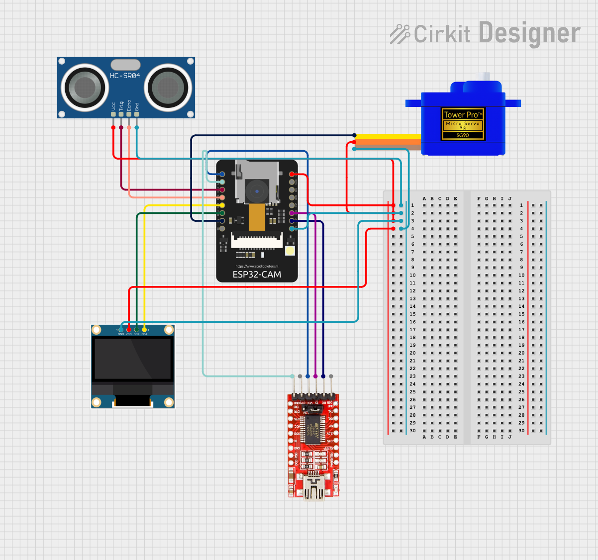
ESP32-CAM Based Ultrasonic Distance Measurement with OLED Display and Servo Control

Circuit Documentation
Summary
The circuit in question is designed to interface an ESP32-CAM module with several peripheral devices, including an FTDI Programmer for serial communication, a 0.96" OLED display for visual output, an HC-SR04 Ultrasonic Sensor for distance measurement, and a Servomotor SG90 for actuation. The ESP32-CAM serves as the central processing unit, controlling the peripherals through its GPIO pins. Power distribution is managed through common VCC and GND lines, and communication with the OLED display is achieved via I2C protocol.
Component List
ESP32 - CAM
- Description: A small-sized ESP32-based module with Wi-Fi and camera capabilities.
- Pins: 5V, GND, IO12, IO13, IO15, IO14, IO2, IO4, VOT, VOR, VCC, IO0, IO16, 3V3
- Purpose: Acts as the main controller for the circuit, handling wireless communication, image capture, and interfacing with other components.
FTDI Programmer
- Description: A USB to serial converter module used for programming devices like the ESP32-CAM.
- Pins: DTR, RX, TX, VCC, CTS, GND
- Purpose: Provides a serial interface for programming and debugging the ESP32-CAM.
0.96" OLED
- Description: A small display module based on OLED technology, capable of showing graphics and text.
- Pins: GND, VDD, SCK, SDA
- Purpose: Displays information and visual feedback from the ESP32-CAM.
HC-SR04 Ultrasonic Sensor
- Description: A sensor module that measures distance by emitting ultrasonic waves and measuring the time taken for the echo to return.
- Pins: VCC, TRIG, ECHO, GND
- Purpose: Provides distance measurements to the ESP32-CAM for processing.
Servomotor SG90
- Description: A small and lightweight servo motor capable of precise angular positioning.
- Pins: SIG, VCC, GND
- Purpose: Executes physical movements under the control of the ESP32-CAM.
Wiring Details
ESP32 - CAM
- 5V connected to FTDI Programmer VCC
- GND connected to FTDI Programmer GND, 0.96" OLED GND, HC-SR04 GND, Servomotor SG90 GND
- IO12 connected to HC-SR04 TRIG
- IO13 connected to HC-SR04 ECHO
- IO15 connected to 0.96" OLED SDA
- IO14 connected to 0.96" OLED SCK
- IO2 connected to Servomotor SG90 SIG
- VOT connected to FTDI Programmer RX
- VOR connected to FTDI Programmer TX
- 3V3 connected to 0.96" OLED VDD, HC-SR04 VCC, Servomotor SG90 VCC
FTDI Programmer
- VCC connected to ESP32 - CAM 5V
- GND connected to ESP32 - CAM GND
- RX connected to ESP32 - CAM VOT
- TX connected to ESP32 - CAM VOR
0.96" OLED
- GND connected to ESP32 - CAM GND
- VDD connected to ESP32 - CAM 3V3
- SCK connected to ESP32 - CAM IO14
- SDA connected to ESP32 - CAM IO15
HC-SR04 Ultrasonic Sensor
- VCC connected to ESP32 - CAM 3V3
- TRIG connected to ESP32 - CAM IO12
- ECHO connected to ESP32 - CAM IO13
- GND connected to ESP32 - CAM GND
Servomotor SG90
- SIG connected to ESP32 - CAM IO2
- VCC connected to ESP32 - CAM 3V3
- GND connected to ESP32 - CAM GND
Documented Code
No code has been provided for the microcontrollers in the circuit. Therefore, this section is currently empty. When code is available, it should be documented here with explanations for each function and routine, as well as the overall logic flow and interaction with the hardware components.