
Arduino Nano Controlled Flame Detection and Motor Management System
View and Edit Project In Cirkit Designer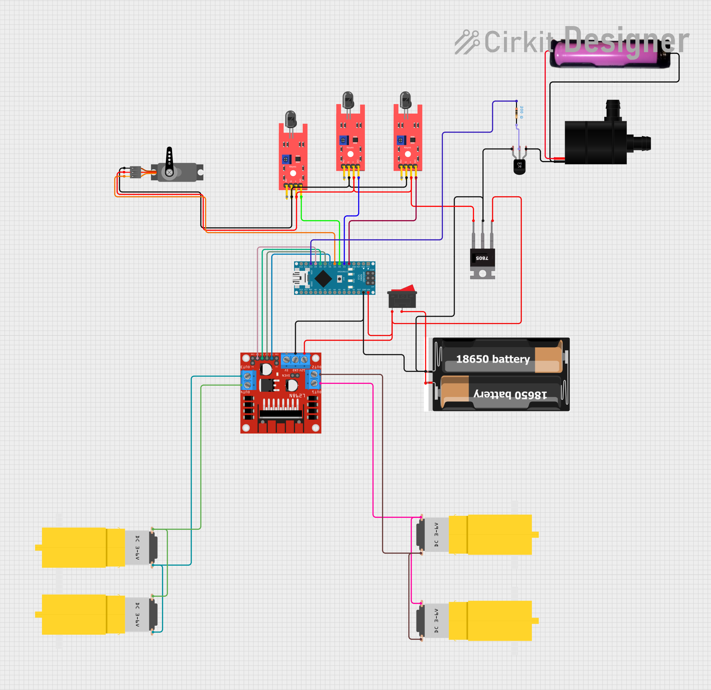
Circuit Documentation
Summary
This circuit integrates various components controlled by an Arduino Nano microcontroller. It includes flame sensors for detecting fire, a servo motor for actuation, a DC motor driver to control hobby motors, a voltage regulator to stabilize the power supply, and a transistor setup to control a water pump. The circuit is powered by 18650 batteries and includes a rocker switch for power control.
Component List
Microcontroller
- Arduino Nano: A compact microcontroller board based on the ATmega328P, featuring digital and analog I/O pins.
Power Supply
- 2x 18650 Batteries: Lithium-ion batteries providing the power source for the circuit.
- 7805 Voltage Regulator: A voltage regulator that outputs a stable 5V from a higher voltage input.
- 18650 Battery Holder: A holder for a single 18650 battery.
Sensors
- KY-026 Flame Sensors: Sensors used for detecting flames or fire.
Motor Control
- L298N DC Motor Driver: A module for controlling DC motors with direction and speed control.
- Hobby Motors: Yellow DC gear motors used for driving mechanical parts.
Actuator
- Servo: A rotary actuator or linear actuator that allows for precise control of angular or linear position.
Switching
- Rocker Switch: A switch to control the power supply to the circuit.
- BC547 Transistor: An NPN transistor used as a switch or amplifier.
- Resistor: A 200 Ohm resistor used for current limiting or voltage division.
Output
- Water Pump: A pump used for moving water, controlled by the transistor.
Wiring Details
Arduino Nano
- Digital pins D2, D3, D4 are connected to the D0 pins of three separate KY-026 Flame Sensors.
- Digital pin D5 is connected to the PWM pin of the Servo.
- Digital pins D6, D7, D8, D9 are connected to the IN1, IN2, IN3, IN4 pins of the L298N DC Motor Driver, respectively.
- Digital pin D10 is connected to one pin of a 200 Ohm Resistor.
- VIN pin is connected to the input of the 7805 Voltage Regulator, the 12V pin of the L298N DC Motor Driver, and one terminal of the Rocker Switch.
- GND pin is connected to the common ground of the circuit.
2x 18650 Batteries
- VCC is connected to one terminal of the Rocker Switch.
- GND is connected to the common ground of the circuit.
KY-026 Flame Sensors
- A0 pins are not connected.
- GND pins are connected to the common ground of the circuit.
- VCC pins are connected to the 5V output of the 7805 Voltage Regulator.
L298N DC Motor Driver
- OUT1 and OUT2 are connected to two Hobby Motors.
- OUT3 and OUT4 are connected to two other Hobby Motors.
- 12V is connected to the VIN pin of the Arduino Nano.
- GND is connected to the common ground of the circuit.
- 5V is not connected.
Hobby Motors
- VCC pins are connected to OUT1/OUT3 of the L298N DC Motor Driver.
- GND pins are connected to OUT2/OUT4 of the L298N DC Motor Driver.
Servo
- GND is connected to the common ground of the circuit.
- VCC is connected to the 5V output of the 7805 Voltage Regulator.
- PWM is connected to the D5 pin of the Arduino Nano.
7805 Voltage Regulator
- Vin is connected to the VIN pin of the Arduino Nano and one terminal of the Rocker Switch.
- Gnd is connected to the common ground of the circuit.
- Vout is connected to the VCC pins of the KY-026 Flame Sensors and the Servo.
Rocker Switch
- Terminal 1 is connected to the VIN pin of the Arduino Nano and the Vin pin of the 7805 Voltage Regulator.
- Terminal 2 is connected to the VCC of the 2x 18650 Batteries.
Water Pump
- VCC is connected to the Collector pin of the BC547 Transistor.
- GND is connected to the common ground of the circuit.
Resistor
- One pin is connected to the D10 pin of the Arduino Nano.
- The other pin is connected to the Base pin of the BC547 Transistor.
BC547 Transistor
- Collector is connected to the VCC pin of the Water Pump.
- Base is connected to one pin of the 200 Ohm Resistor.
- Emitter is connected to the common ground of the circuit.
18650 Battery Holder
- VCC is connected to the VCC pin of the Water Pump.
- GND is connected to the common ground of the circuit.
Documented Code
Arduino Nano - sketch.ino
void setup() {
  // put your setup code here, to run once:

}

void loop() {
  // put your main code here, to run repeatedly:

}
Arduino Nano - documentation.txt
(No additional documentation provided for the code)
(Note: The code provided is a template and does not include any functionality. Additional code is required to control the components based on the circuit design.)