
18650 Li-ion Battery-Powered BMS with Boost Converter and 5V Adapter
View and Edit Project In Cirkit Designer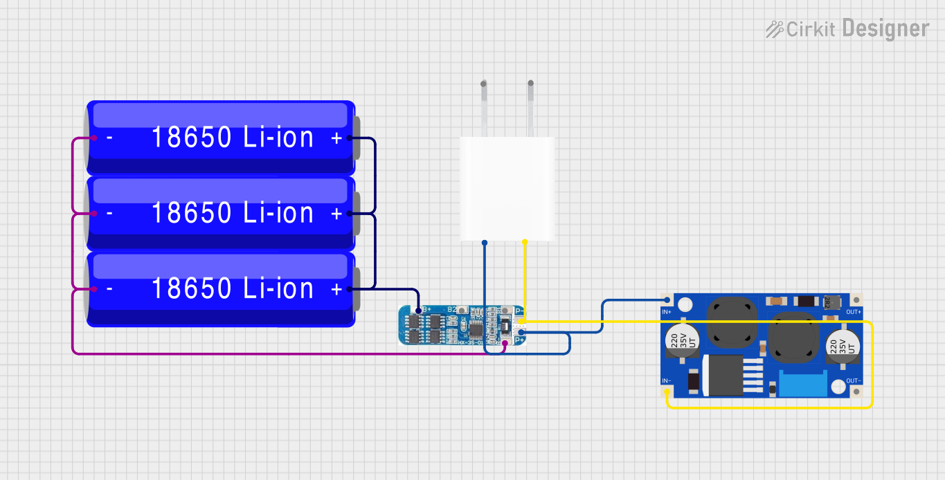
Circuit Documentation
Summary of the Circuit
This circuit is designed to utilize three 18650 Li-ion batteries in conjunction with a Battery Management System (BMS) to provide a stable power source. The BMS ensures safe charging and discharging of the batteries. The output from the BMS is then fed into an XL6009E1 Boost Converter to step up the voltage to a desired level. Additionally, a 5V Adapter is included in the circuit to provide a regulated 5V output. This circuit could be used in portable electronics, DIY power banks, or any application requiring a rechargeable battery pack with a higher voltage output.
Component List
18650 Li-ion Battery
- Description: A rechargeable lithium-ion cell commonly used in high-drain applications.
- Pins: Negative (-), Positive (+)
BMS (Battery Management System)
- Description: A system that manages a rechargeable battery by protecting the battery from operating outside its safe operating area.
- Pins: B+, B2, B1, B-, P-, P+
XL6009E1 Boost Converter
- Description: A DC-DC converter that steps up the input voltage to a higher output voltage.
- Pins: IN+, IN-, OUT-, OUT+
5V Adapter
- Description: An adapter that converts AC input to a regulated 5V DC output.
- Pins: AC In 1, AC In 2, 5V, GND
Wiring Details
18650 Li-ion Battery
- Negative (-): Connected to the BMS B- pin.
- Positive (+): Connected to the BMS B+ pin.
BMS (Battery Management System)
- B-: Connected to the negative (-) pins of all three 18650 Li-ion Batteries.
- B+: Connected to the positive (+) pins of all three 18650 Li-ion Batteries.
- P-: Connected to the GND pin of the 5V Adapter and the IN- pin of the XL6009E1 Boost Converter.
- P+: Connected to the 5V pin of the 5V Adapter and the IN+ pin of the XL6009E1 Boost Converter.
XL6009E1 Boost Converter
- IN+: Connected to the P+ pin of the BMS.
- IN-: Connected to the P- pin of the BMS.
- OUT-: Not connected in the provided net list.
- OUT+: Not connected in the provided net list.
5V Adapter
- AC In 1 & AC In 2: These pins would typically be connected to an AC power source, but specific wiring details are not provided in the net list.
- 5V: Connected to the P+ pin of the BMS.
- GND: Connected to the P- pin of the BMS.
Documented Code
No code has been provided for any microcontrollers in the circuit. If there are any embedded systems or programmable components involved in this circuit, their code is not included in the documentation inputs.