ESP8266-Based Environmental Monitoring System with Motion Detection
Circuit Documentation
Summary
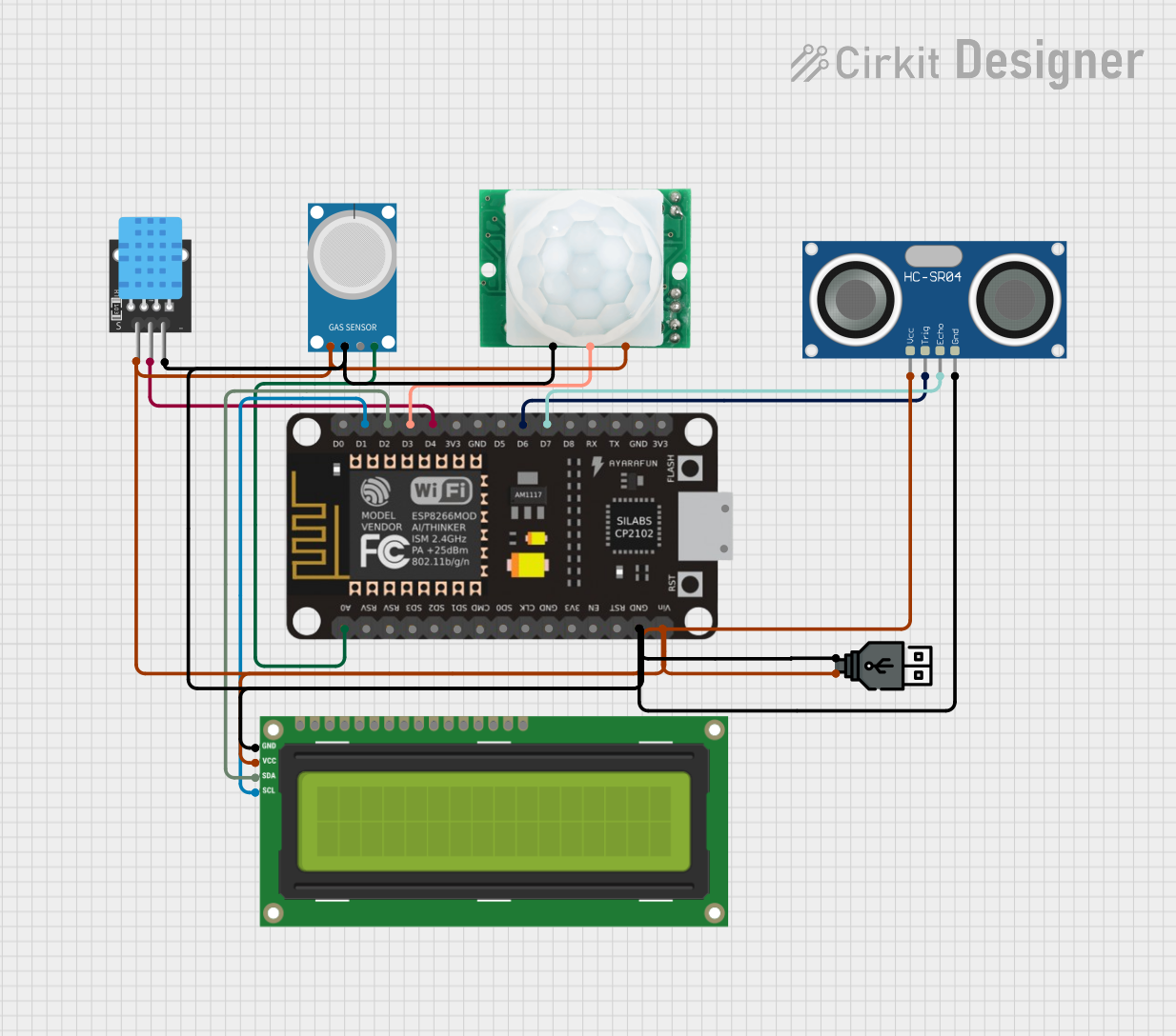
The circuit in question is designed to interface various sensors and an I2C LCD screen with an ESP-8266 microcontroller. The sensors include an MQ-4 gas sensor, an HC-SR04 ultrasonic sensor, a DHT11 temperature and humidity sensor, and an HC-SR501 motion sensor. The circuit is powered via a USB power module. The ESP-8266 controller serves as the central processing unit, reading data from the sensors, and displaying information on the I2C LCD screen. The circuit is designed for monitoring environmental parameters and displaying them or triggering actions based on sensor inputs.
Component List
I2C LCD 16x2 Screen
- Description: A 16x2 character LCD display that uses the I2C communication protocol.
- Pins: SCL, SDA, VCC (5V), GND, VDD, VO, RS, RW, E, D0-D7, BLA, BLK
ESP-8266 Controller
- Description: A Wi-Fi capable microcontroller with a variety of digital and analog pins.
- Pins: A0, RSV, SD3, SD5, SD1, CMD, D0-D8, RX, TX, Vin, 3V3, GND, 5V
MQ-4 Gas Sensor
- Description: A sensor for detecting methane and natural gas in the air.
- Pins: A0, D0, GND, VCC
HC-SR04 Ultrasonic Sensor
- Description: A sensor for measuring distance via ultrasonic waves.
- Pins: VCC, TRIG, ECHO, GND
DHT11 Temperature and Humidity Sensor
- Description: A sensor for measuring ambient temperature and humidity.
- Pins: 5V, S, GND
HC-SR501 Motion Sensor
- Description: A passive infrared sensor for detecting motion.
- Pins: GND, OUT, VCC
USB Power
- Description: A power module for supplying the circuit via a USB connection.
- Pins: +, -
Wiring Details
I2C LCD 16x2 Screen
- SCL connected to ESP-8266 Controller (D1)
- SDA connected to ESP-8266 Controller (D2)
- VCC (5V) connected to USB Power (+)
- GND connected to USB Power (-)
ESP-8266 Controller
- A0 connected to MQ-4 (A0)
- D1 connected to I2C LCD 16x2 Screen (SCL)
- D2 connected to I2C LCD 16x2 Screen (SDA)
- Vin connected to USB Power (+)
- GND connected to USB Power (-)
- D3 connected to HC-SR501 Motion Sensor (OUT)
- D4 connected to DHT11 (S)
- D6 connected to HC-SR04 Ultrasonic Sensor (TRIG)
- D7 connected to HC-SR04 Ultrasonic Sensor (ECHO)
MQ-4 Gas Sensor
- VCC connected to USB Power (+)
- GND connected to USB Power (-)
- A0 connected to ESP-8266 Controller (A0)
HC-SR04 Ultrasonic Sensor
- VCC connected to USB Power (+)
- TRIG connected to ESP-8266 Controller (D6)
- ECHO connected to ESP-8266 Controller (D7)
- GND connected to USB Power (-)
DHT11 Temperature and Humidity Sensor
- 5V connected to USB Power (+)
- S connected to ESP-8266 Controller (D4)
- GND connected to USB Power (-)
HC-SR501 Motion Sensor
- VCC connected to USB Power (+)
- OUT connected to ESP-8266 Controller (D3)
- GND connected to USB Power (-)
USB Power
- connected to VCC of ESP-8266 Controller, MQ-4, HC-SR04, DHT11, I2C LCD 16x2 Screen, and HC-SR501
- connected to GND of ESP-8266 Controller, MQ-4, HC-SR04, DHT11, I2C LCD 16x2 Screen, and HC-SR501
Documented Code
No code has been provided for the microcontroller. The code would typically initialize the sensors, handle data acquisition, process the data, and manage communication with the I2C LCD screen to display the sensor readings. It would also include setup for Wi-Fi connectivity and any web server or MQTT functionalities if needed for remote monitoring or control.