
Arduino Mega 2560-Based Interactive Game with RGB LEDs, LCD Display, and DFPlayer Audio
View and Edit Project In Cirkit Designer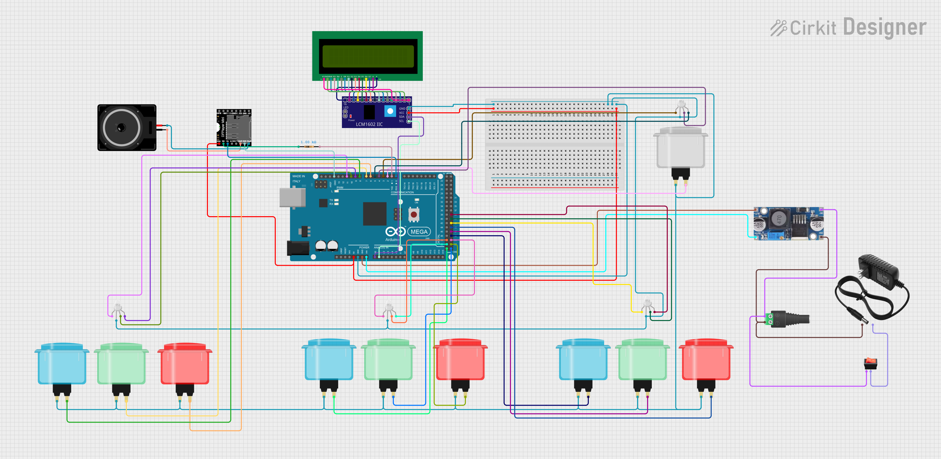
Circuit Documentation
Summary
This circuit is designed to control an RGB LED, read button inputs from three players, display the winner's name on an LCD, and play the winner's name using a DFPlayer module. The circuit is powered by a 12V power supply, which is stepped down to 5V using a buck converter to power the Arduino Mega 2560 and other components.
Component List
RGB LED (Wokwi compatible)
- Pins: R, COM, G, B
- Description: RGB LED used to display different colors based on the player's input.
Arcade Button (green)
- Pins: no name yet
- Description: Green arcade button used for player input.
Arcade Button (white)
- Pins: no name yet
- Description: White arcade button used for player input.
Arcade Button (red)
- Pins: no name yet
- Description: Red arcade button used for player input.
Arcade Button (blue)
- Pins: no name yet
- Description: Blue arcade button used for player input.
Rocker Switch
- Pins: output, input
- Description: Rocker switch used to control the power supply.
Loudspeaker
- Pins: pin1, pin2
- Description: Loudspeaker used to play audio from the DFPlayer module.
2.1mm Barrel Jack with Terminal Block
- Pins: POS, NEG
- Description: Barrel jack used to connect the 12V power supply.
16X2 LCD
- Pins: VSS, VDD, V0, RS, RW, E, D1, D0, D2, D3, D4, D6, D5, D7, A, K
- Description: LCD used to display the winner's name.
12V Power Supply
- Pins: +, -
- Description: Power supply providing 12V to the circuit.
DFPlayer MINI
- Pins: VCC, BUSY, RX, USB -, TX, USB +, DAC_R, K2/ADC_KEY, DAC_L, K1/ADC_KEY, SPK1, IO 2, GND, SPK2, IO 1
- Description: Audio module used to play audio files.
Step Down Buck Converter
- Pins: IN +, IN - GND, OUT +, OUT - GND
- Description: Buck converter used to step down 12V to 5V.
Arduino Mega 2560
- Pins: IOREF, RESET, 3V3, 5V, GND, VIN, A0, A1, A2, A3, A4, A5, A6, A7, A8, A9, A10, A11, A12, A13, A14, A15, D21/SCL, D20/SDA, D19/RX1, D18/TX1, D17 PWM/RX2, D16 PWM/TX2, D15/RX3, D14/TX3, D0 RX0, D1 TX0, D2 PWM, D3 PWM, D4 PWM, D5 PWM, D6 PWM, D7 PWM, D8 PWM, D9 PWM, D10 PWM, D11 PWM, D12 PWM, D13 PWM, AREF, SDA, SCL, D52, D50, D48, D46, D44, D42, D40, D38, D36, D34, D32, D30, D28, D26, D24, D22, D53, D51, D49, D47, D45, D43, D41, D39, D37, D35, D33, D31, D29, D27, D25, D23
- Description: Microcontroller used to control the circuit.
LCM1602 IIC
- Pins: GND, VCC, SDA, SCL, D6, D7, A, K, VSS, VDD, V0, RS, D2, D3, D4, D5, RW, E, D0, D1, LED_A, LED_B
- Description: I2C interface for the 16X2 LCD.
Resistor
- Pins: pin1, pin2
- Description: Resistor used to limit current.
- Properties: Resistance: 1000 Ohms
Wiring Details
RGB LED (Wokwi compatible)
- R: Connected to Arduino Mega 2560 D51
- COM: Connected to GND
- G: Connected to Arduino Mega 2560 D50
- B: Connected to Arduino Mega 2560 D52
RGB LED (Wokwi compatible)
- R: Connected to Arduino Mega 2560 D3 PWM
- COM: Connected to GND
- G: Connected to Arduino Mega 2560 D4 PWM
- B: Connected to Arduino Mega 2560 D5 PWM
RGB LED (Wokwi compatible)
- R: Connected to Arduino Mega 2560 D43
- COM: Connected to GND
- G: Connected to Arduino Mega 2560 D41
- B: Connected to Arduino Mega 2560 D39
RGB LED (Wokwi compatible)
- R: Connected to Arduino Mega 2560 D11 PWM
- COM: Connected to GND
- G: Connected to Arduino Mega 2560 D10 PWM
- B: Connected to Arduino Mega 2560 D9 PWM
Arcade Button (green)
- Pin: Connected to Arduino Mega 2560 D47
- Pin: Connected to GND
Arcade Button (white)
- Pin: Connected to Arduino Mega 2560 D2 PWM
- Pin: Connected to GND
Arcade Button (red)
- Pin: Connected to Arduino Mega 2560 D6 PWM
- Pin: Connected to GND
Arcade Button (blue)
- Pin: Connected to Arduino Mega 2560 D8 PWM
- Pin: Connected to GND
Rocker Switch
- Output: Connected to 12V power supply -
- Input: Connected to 2.1mm Barrel Jack with Terminal Block POS
Loudspeaker
- Pin1: Connected to DFPlayer MINI SPK1
- Pin2: Connected to DFPlayer MINI SPK2
2.1mm Barrel Jack with Terminal Block
- POS: Connected to Step Down Buck Converter IN - GND
- NEG: Connected to Step Down Buck Converter IN +
16X2 LCD
- VSS: Connected to LCM1602 IIC VSS
- VDD: Connected to LCM1602 IIC VDD
- V0: Connected to LCM1602 IIC V0
- RS: Connected to LCM1602 IIC RS
- RW: Connected to LCM1602 IIC RW
- E: Connected to LCM1602 IIC E
- D1: Connected to LCM1602 IIC D1
- D0: Connected to LCM1602 IIC D0
- D2: Connected to LCM1602 IIC D2
- D3: Connected to LCM1602 IIC D3
- D4: Connected to LCM1602 IIC D4
- D6: Connected to LCM1602 IIC D6
- D5: Connected to LCM1602 IIC D5
- D7: Connected to LCM1602 IIC D7
- A: Connected to LCM1602 IIC A
- K: Connected to LCM1602 IIC K
12V Power Supply
- +: Connected to 2.1mm Barrel Jack with Terminal Block NEG
- -: Connected to Rocker Switch output
DFPlayer MINI
- VCC: Connected to Arduino Mega 2560 5V
- BUSY: Not connected
- RX: Connected to Resistor pin1
- USB -: Not connected
- TX: Connected to Arduino Mega 2560 D0 RX0
- USB +: Not connected
- DAC_R: Not connected
- K2/ADC_KEY: Not connected
- DAC_L: Not connected
- K1/ADC_KEY: Not connected
- SPK1: Connected to Loudspeaker pin1
- IO 2: Not connected
- GND: Connected to Arduino Mega 2560 GND
- SPK2: Connected to Loudspeaker pin2
- IO 1: Not connected
Step Down Buck Converter
- **IN +