Arduino UNO R4 WiFi-Based Environmental Monitoring System with GPS and Data Logging
Circuit Documentation
Summary
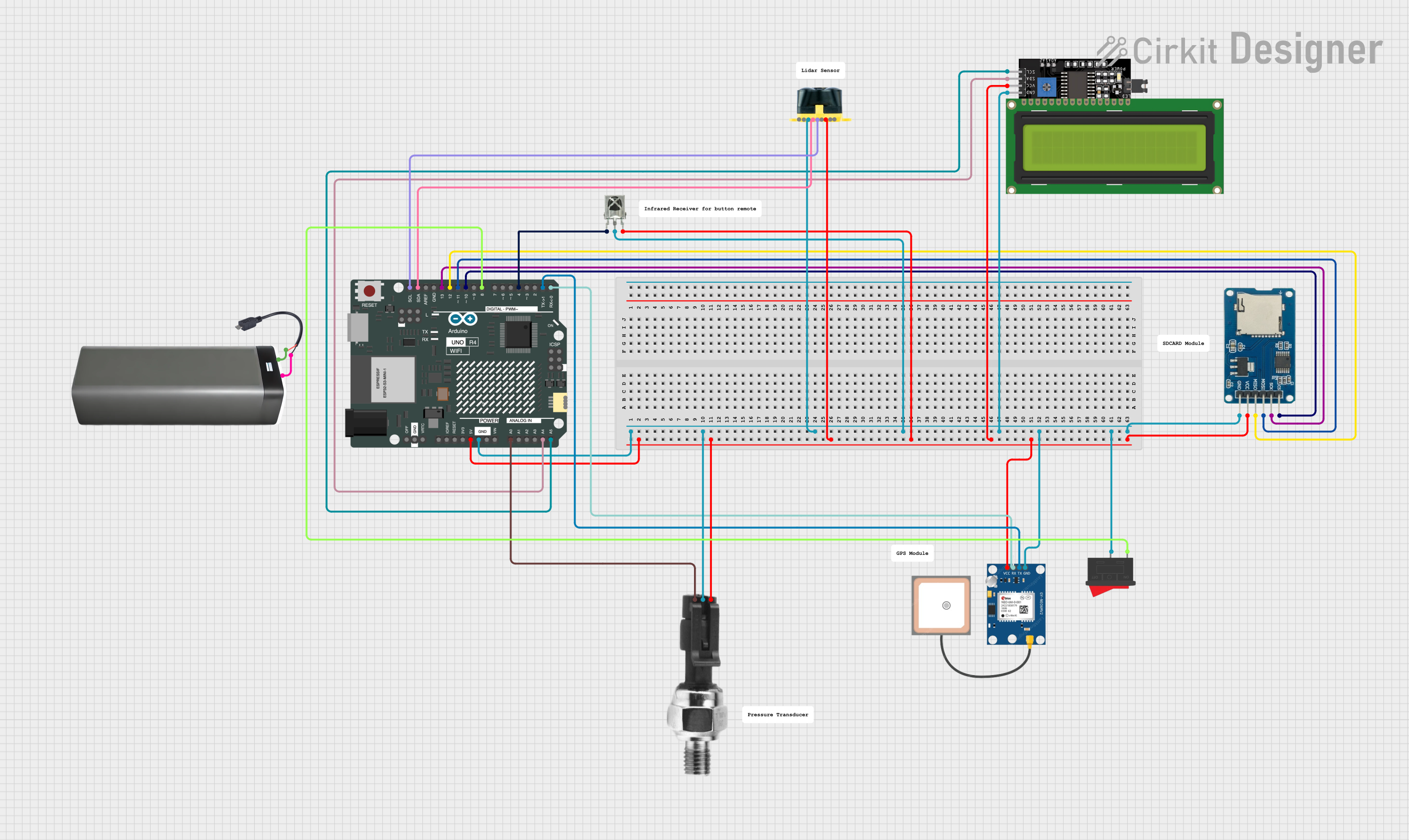
This circuit is designed to collect data from an industrial pressure sensor and a GPS module, receive signals from an IR receiver, and display information on an LCD screen. The data is logged to an SD card for record-keeping. The system's operation can be controlled using a rocker switch. An Arduino UNO R4 WiFi serves as the central microcontroller unit, interfacing with the various sensors, the display, and the SD card module. The circuit is powered by a battery pack connected through a Micro USB to Cable (2 Pin).
Component List
Arduino UNO R4 WiFi
- Microcontroller board with WiFi capability.
- It has a variety of digital and analog pins for interfacing with other components.
Industrial Pressure Sensor
- Measures pressure and outputs a corresponding electrical signal.
Micro SD Card Module
- Used for data logging.
- Interfaces with the Arduino via SPI.
VS1838B IR Receiver
- Receives infrared signals.
- Outputs a signal to the Arduino when an IR signal is detected.
LCD Display 16x4 I2C
- Displays text and numbers.
- Uses I2C for communication with the Arduino.
Battery Pack
- Provides power to the circuit.
Micro USB to Cable (2 Pin)
- Connects the battery pack to the circuit.
Rocker Switch
- Controls the power to the circuit.
GPS NEO 6M
- GPS module for location tracking.
- Communicates with the Arduino via serial connection.
Evo 15m
- A sensor or module (not specified), interfacing with the Arduino.
Wiring Details
Arduino UNO R4 WiFi
- GND connected to the ground of all components.
- 5V connected to the VCC of all components.
- A0 connected to the signal output of the Industrial Pressure Sensor.
- A4 (SDA) and A5 (SCL) connected to the I2C pins of the LCD Display.
- D0/RX and D1/TX connected to the TX and RX of the GPS NEO 6M, respectively.
- D4 connected to the output of the VS1838B IR Receiver.
- D8 connected to one pin of the Rocker Switch.
- D10 (cs), D11 (mosi), D12 (miso), and D13 (sck) connected to the corresponding pins of the Micro SD Card Module.
Industrial Pressure Sensor
- DC+ and DC- connected to 5V and GND, respectively.
- Signal connected to A0 on the Arduino.
Micro SD Card Module
- cs, sck, mosi, miso, vcc, and gnd connected to the corresponding pins on the Arduino.
VS1838B IR Receiver
- OUT connected to D4 on the Arduino.
- GND and VCC connected to the common ground and 5V rails, respectively.
LCD Display 16x4 I2C
- SDA and SCL connected to A4 and A5 on the Arduino (I2C bus).
- VCC and GND connected to the power rails.
Battery Pack
- + and - connected to the Micro USB to Cable (2 Pin).
Micro USB to Cable (2 Pin)
- Micro USB not connected in the provided net list.
- + and - connected to the Battery Pack.
Rocker Switch
- One pin connected to D8 on the Arduino.
- The other pin not connected in the provided net list.
GPS NEO 6M
- VCC and GND connected to the power rails.
- RX and TX connected to D0/RX and D1/TX on the Arduino.
Evo 15m
- Pins connected to the Arduino not specified in the provided net list.
Documented Code
/*
 * This Arduino sketch reads data from a pressure sensor, GPS module, and IR receiver.
 * It displays the distance from the ground and temperature on an LCD screen.
 * The data is also logged to an SD card along with GPS information.
 * The system can be turned on and off using a rocker switch.
 */

#include <Wire.h>
#include <LiquidCrystal_I2C.h>
#include <SD.h>
#include <SPI.h>
#include <SoftwareSerial.h>

// Pin definitions
const int pressureSensorPin = A0;
const int irReceiverPin = 4;
const int rockerSwitchPin = 8;
const int chipSelect = 10;
const int gpsRxPin = 0;
const int gpsTxPin = 1;

// LCD setup
LiquidCrystal_I2C lcd(0x27, 16, 4);

// GPS setup
SoftwareSerial gpsSerial(gpsRxPin, gpsTxPin);

void setup() {
  // Initialize serial communication
  Serial.begin(9600);
  gpsSerial.begin(9600);

  // Initialize LCD
  lcd.begin();
  lcd.backlight();

  // Initialize SD card
  if (!SD.begin(chipSelect)) {
    Serial.println("SD card initialization failed!");
    return;
  }
  Serial.println("SD card initialized.");

  // Initialize pins
  pinMode(pressureSensorPin, INPUT);
  pinMode(irReceiverPin, INPUT);
  pinMode(rockerSwitchPin, INPUT);
}

void loop() {
  // Check if the rocker switch is on
  if (digitalRead(rockerSwitchPin) == HIGH) {
    // Read pressure sensor value
    int pressureValue = analogRead(pressureSensorPin);
    float distance = calculateDistance(pressureValue);
    float temperature = readTemperature();

    // Read GPS data
    String gpsData = readGPSData();

    // Display data on LCD
    lcd.setCursor(0, 0);
    lcd.print("Dist: ");
    lcd.print(distance);
    lcd.print(" cm");
    lcd.setCursor(0, 1);
    lcd.print("Temp: ");
    lcd.print(temperature);
    lcd.print(" C");

    // Log data to SD card
    logDataToSD(distance, temperature, gpsData);
  }
  delay(1000); // Delay for 1 second
}

float calculateDistance(int sensorValue) {
  // Convert sensor value to distance (example conversion)
  return sensorValue * 0.1;
}

float readTemperature() {
  // Placeholder for temperature reading logic
  return 25.0; // Example temperature
}

String readGPSData() {
  String gpsData = "";
  while (gpsSerial.available()) {
    char c = gpsSerial.read();
    gpsData += c;
  }
  return gpsData;
}

void logDataToSD(float distance, float temperature, String gpsData) {
  File dataFile = SD.open("datalog.txt", FILE_WRITE);
  if (dataFile) {
    dataFile.print("Distance: ");
    dataFile.print(distance);
    dataFile.print(" cm, Temperature: ");
    dataFile.print(temperature);
    dataFile.print(" C, GPS: ");
    dataFile.println(gpsData);
    dataFile.close();
  } else {
    Serial.println("Error opening datalog.txt");
  }
}
This code is responsible for the operation of the Arduino UNO R4 WiFi in the circuit. It initializes the connected components, reads sensor data, displays information on the LCD, and logs data to the SD card. The code includes functions for calculating distance from the pressure sensor reading, reading temperature (placeholder), reading GPS data, and logging data to the SD card. The system's operation can be toggled using the rocker switch.