
Arduino and ESP8266-Based Smart Sensor System with Solar Power
View and Edit Project In Cirkit Designer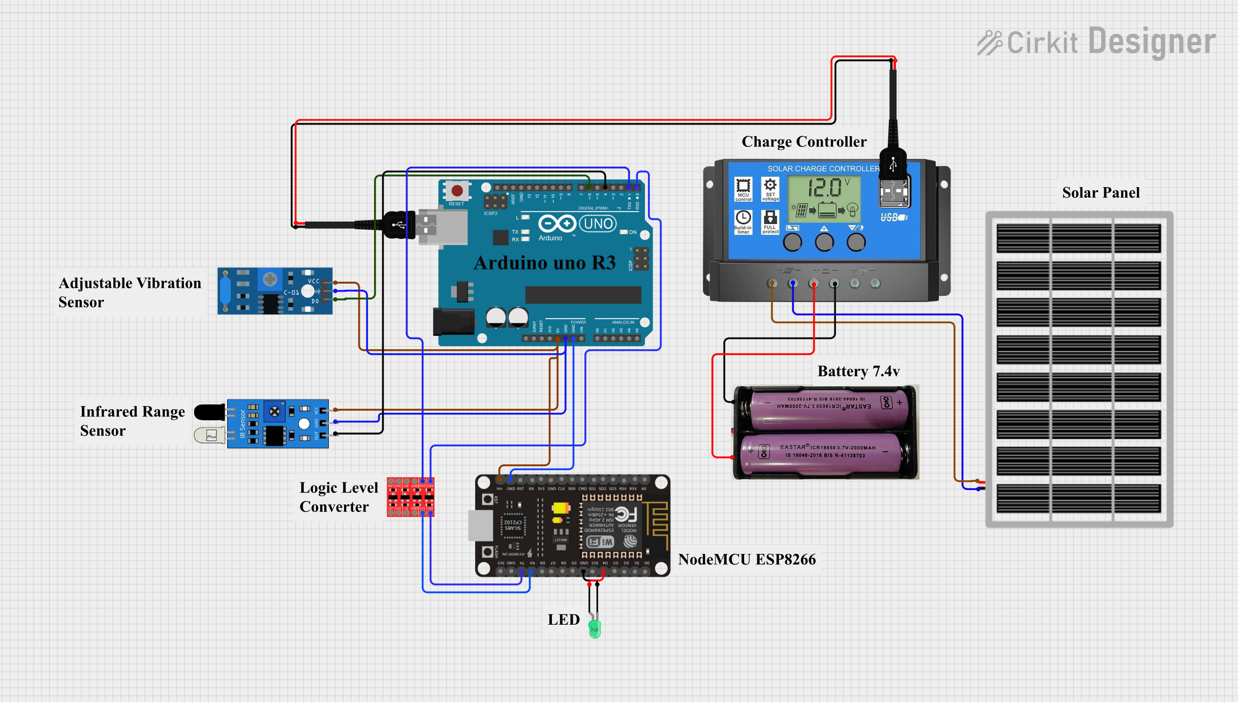
Circuit Documentation
Summary
This circuit integrates an Arduino UNO, an ESP8266 NodeMCU, a SW-420 Vibration Sensor, an IR Sensor, a Solar Panel, a Solar Charge Controller, a Bi-Directional Logic Level Converter, and a green LED. The circuit is designed to monitor vibrations and infrared signals, and it is powered by a solar panel with a charge controller. The ESP8266 NodeMCU is used for wireless communication, and the Arduino UNO serves as the main microcontroller.
Component List
Arduino UNO
- Description: A microcontroller board based on the ATmega328P.
- Pins: UNUSED, IOREF, Reset, 3.3V, 5V, GND, Vin, A0, A1, A2, A3, A4, A5, SCL, SDA, AREF, D13, D12, D11, D10, D9, D8, D7, D6, D5, D4, D3, D2, D1, D0
ESP8266 NodeMCU
- Description: A low-cost Wi-Fi microchip with full TCP/IP stack and microcontroller capability.
- Pins: D0, D1, D2, D3, D4, 3V3, GND, D5, D6, D7, D8, RX, TX, A0, RSV, SD3, SD2, SD1, CMD, SD0, CLK, EN, RST, VIN
SW-420 Vibration Sensor
- Description: A vibration sensor module that detects vibrations and outputs a digital signal.
- Pins: vcc, Ground, Digital output
IR Sensor
- Description: An infrared sensor module that detects objects and outputs a digital signal.
- Pins: out, gnd, vcc
Solar Panel
- Description: A device that converts sunlight into electrical energy.
- Pins: gnd, vcc
Solar Charge Controller
- Description: A device that regulates the voltage and current coming from the solar panels to the battery.
- Pins: Solar Cell +, Solar Cell -, Battery +, Battery -, Load +, Load -
Bi-Directional Logic Level Converter
- Description: A module that safely steps down 5V signals to 3.3V and steps up 3.3V to 5V.
- Pins: HV1, HV2, HV, GND, HV3, HV4, LV1, LV2, LV, LV3, LV4
LED: Two Pin (green)
- Description: A green light-emitting diode.
- Pins: cathode, anode
7.4V Battery
- Description: A rechargeable battery providing 7.4V.
- Pins: +, -
USB Male 2 Pin Connection
- Description: A USB male connector with two pins.
- Pins: Negative -, Positive +
Wiring Details
Arduino UNO
- 5V connected to VIN of ESP8266 NodeMCU, vcc of IR Sensor, and vcc of SW-420 Vibration Sensor.
- GND connected to GND of ESP8266 NodeMCU, gnd of IR Sensor, and Ground of SW-420 Vibration Sensor.
- D6 connected to Digital output of SW-420 Vibration Sensor.
- D4 connected to out of IR Sensor.
- D1 connected to HV3 of Bi-Directional Logic Level Converter.
- D0 connected to HV4 of Bi-Directional Logic Level Converter.
ESP8266 NodeMCU
- VIN connected to 5V of Arduino UNO, vcc of IR Sensor, and vcc of SW-420 Vibration Sensor.
- GND connected to GND of Arduino UNO, cathode of LED.
- D4 connected to anode of LED.
- RX connected to LV3 of Bi-Directional Logic Level Converter.
- TX connected to LV4 of Bi-Directional Logic Level Converter.
SW-420 Vibration Sensor
- vcc connected to 5V of Arduino UNO, VIN of ESP8266 NodeMCU, and vcc of IR Sensor.
- Ground connected to GND of Arduino UNO, GND of ESP8266 NodeMCU, and gnd of IR Sensor.
- Digital output connected to D6 of Arduino UNO.
IR Sensor
- vcc connected to 5V of Arduino UNO, VIN of ESP8266 NodeMCU, and vcc of SW-420 Vibration Sensor.
- gnd connected to GND of Arduino UNO, GND of ESP8266 NodeMCU, and Ground of SW-420 Vibration Sensor.
- out connected to D4 of Arduino UNO.
Solar Panel
- gnd connected to Solar Cell - of Solar Charge Controller.
- vcc connected to Solar Cell + of Solar Charge Controller.
Solar Charge Controller
- Solar Cell - connected to gnd of Solar Panel.
- Solar Cell + connected to vcc of Solar Panel.
- Battery + connected to + of 7.4V Battery.
- Battery - connected to - of 7.4V Battery.
Bi-Directional Logic Level Converter
- HV3 connected to D1 of Arduino UNO.
- HV4 connected to D0 of Arduino UNO.
- LV3 connected to RX of ESP8266 NodeMCU.
- LV4 connected to TX of ESP8266 NodeMCU.
LED: Two Pin (green)
- anode connected to D4 of ESP8266 NodeMCU.
- cathode connected to GND of ESP8266 NodeMCU.
7.4V Battery
- + connected to Battery + of Solar Charge Controller.
- - connected to Battery - of Solar Charge Controller.
USB Male 2 Pin Connection
- Negative - connected to Negative - of another USB Male 2 Pin Connection.
- Positive + connected to Positive + of another USB Male 2 Pin Connection.
Documented Code
Arduino UNO Code
void setup() {
  // put your setup code here, to run once:

}

void loop() {
  // put your main code here, to run repeatedly:

}
Documentation File
- File Name: documentation.txt
- Content: (Empty)