
ESP32-Based Environmental Monitoring System with Multiple Sensors and OLED Display
View and Edit Project In Cirkit Designer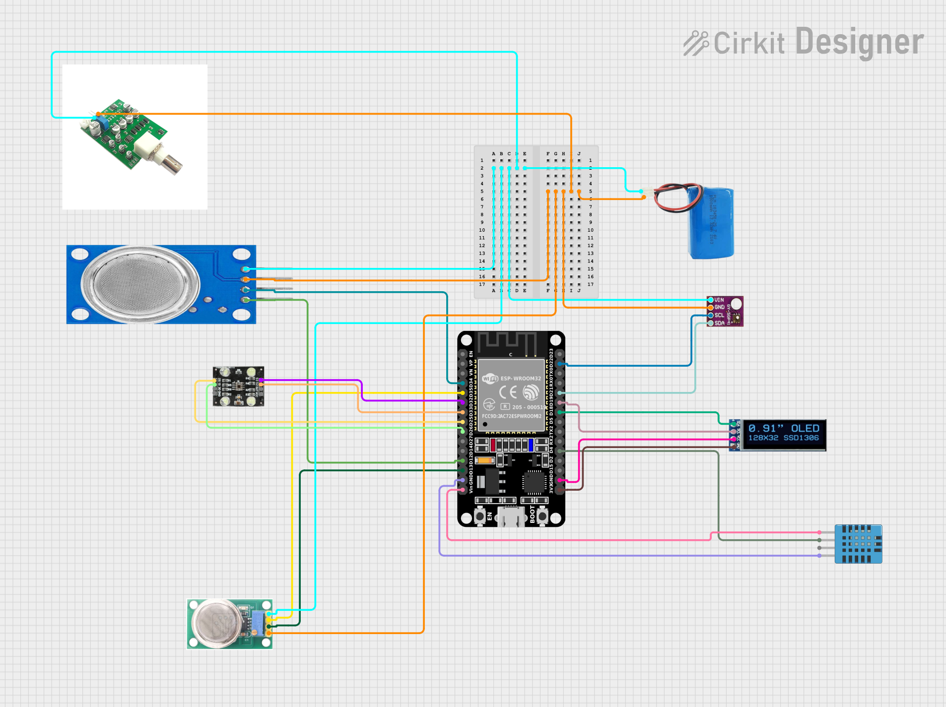
Circuit Documentation
Summary
This document provides a detailed overview of a circuit that includes various sensors, a display, and an ESP32 microcontroller. The circuit is designed to collect environmental data such as temperature, humidity, VOC, and NOx levels, and display the information on an OLED screen. The ESP32 microcontroller is also equipped with Bluetooth capabilities for remote data transmission.
Component List
MQ-136
- Description: Gas sensor for detecting hydrogen sulfide (H2S).
- Pins: GND, OUT1, OUT2, VCC
DHT11 Humidity and Temperature Sensor
- Description: Sensor for measuring humidity and temperature.
- Pins: VDD, DATA, NULL, GND
SGP41 VOC and NOx Sensor
- Description: Sensor for detecting volatile organic compounds (VOC) and nitrogen oxides (NOx).
- Pins: VIN, GND, SCL, SDA
OLED Display 128x32
- Description: 128x32 pixel OLED display.
- Pins: SDA, SCL, VCC, GND
ESP32 (30 pin)
- Description: Microcontroller with built-in Wi-Fi and Bluetooth capabilities.
- Pins: EN, VP, VN, D34, D35, D32, D33, D25, D26, D27, D14, D12, D13, GND, Vin, D23, D22, TX0, RX0, D21, D19, D18, D5, TX2, RX2, D4, D2, D15, 3V3
5V Battery
- Description: Power source for the circuit.
- Pins: Positive, Negative
MQ135
- Description: Gas sensor for detecting air quality.
- Pins: VCC, GND, A0, D0
pH Module
- Description: Module for measuring pH levels.
- Pins: GND, VCC
TCS230
- Description: Color sensor.
- Pins: GND, OE, S1, S0, VCC, OUT, S2, S3
Wiring Details
MQ-136
- GND: Connected to the common ground.
- OUT1: Connected to ESP32 pin D13.
- OUT2: Connected to ESP32 pin D35.
- VCC: Connected to the positive terminal of the 5V battery.
DHT11 Humidity and Temperature Sensor
- VDD: Connected to ESP32 pin Vin.
- DATA: Connected to ESP32 pin D4.
- GND: Connected to ESP32 ground.
SGP41 VOC and NOx Sensor
- VIN: Connected to the positive terminal of the 5V battery.
- GND: Connected to the common ground.
- SCL: Connected to ESP32 pin D22.
- SDA: Connected to ESP32 pin D21.
OLED Display 128x32
- SDA: Connected to ESP32 pin D18.
- SCL: Connected to ESP32 pin D19.
- VCC: Connected to ESP32 ground.
- GND: Connected to ESP32 pin 3V3.
ESP32 (30 pin)
- D34: Connected to MQ135 pin A0.
- D35: Connected to MQ-136 pin OUT2.
- D32: Connected to TCS230 pin S3.
- D33: Connected to TCS230 pin S2.
- D25: Connected to TCS230 pin S0.
- D26: Connected to TCS230 pin S1.
- D12: Connected to MQ135 pin D0.
- D13: Connected to MQ-136 pin OUT1.
- GND: Connected to DHT11 GND, OLED VCC.
- Vin: Connected to DHT11 VDD.
- D22: Connected to SGP41 pin SCL.
- D21: Connected to SGP41 pin SDA.
- D19: Connected to OLED pin SCL.
- D18: Connected to OLED pin SDA.
- D4: Connected to DHT11 pin DATA.
- 3V3: Connected to OLED pin GND.
5V Battery
- Positive: Connected to SGP41 pin VIN, MQ135 pin VCC, pH Module pin VCC, MQ-136 pin VCC.
- Negative: Connected to SGP41 pin GND, MQ135 pin GND, pH Module pin GND, MQ-136 pin GND.
MQ135
- VCC: Connected to the positive terminal of the 5V battery.
- GND: Connected to the common ground.
- A0: Connected to ESP32 pin D34.
- D0: Connected to ESP32 pin D12.
pH Module
- GND: Connected to the common ground.
- VCC: Connected to the positive terminal of the 5V battery.
TCS230
- GND: Connected to the common ground.
- S3: Connected to ESP32 pin D32.
- S2: Connected to ESP32 pin D33.
- S0: Connected to ESP32 pin D25.
- S1: Connected to ESP32 pin D26.
- VCC: Connected to the positive terminal of the 5V battery.
Code Documentation
// The script is written by Slavko Zdravevski
// If you want to support my work, you can subscribe to my youtube channel: https://bit.ly/3FG9hpK
// I do a lot of interesting things in my free time, so you might find something of your interest or we can exchange ideas and knowledge

// Libraries, I also put them on github
#include "BluetoothSerial.h"
#include <RCSwitch.h>

// Pinout declaration
int ledPin = 13;
int rfReceiverPin = 2;
int rfTransmitterPin = 4;

// Additional variables needed through the code
unsigned long currentSecounds, previousSecoundsRecord;
String receivedCommand;
String commandToSend;

unsigned long receivedCodes[100];
int receivedProtocols[100];
int receiverCounter = 0;
bool canStoreCurrentCode = true;
unsigned long previousMillisLed = 0;
bool blinkLed = false;
int ledCounter = 0;

BluetoothSerial SerialBT;
RCSwitch mySwitch = RCSwitch();

void setup() {
  Serial.begin(115200);
  SerialBT.begin("ESP32"); // If you want to use my app, leave this line as it is, otherwise, it won't work
  mySwitch.enableReceive(rfReceiverPin);
  mySwitch.enableTransmit(rfTransmitterPin);
  pinMode(ledPin, OUTPUT);
}

void loop() {
  currentSecounds = millis() / 1000;
  receiveBtData();
  decodeRfSignals();
  checkLedState();

  if ((currentSecounds - previousSecoundsRecord) >= 4) {
    previousSecoundsRecord = currentSecounds;
    SerialBT.println("Good connection");
  }
}

// Method declarations
void receiveBtData() { // Receives Bluetooth data sent from the Android device and acts accordingly
  if (SerialBT.available()) {
    receivedCommand += String((char)SerialBT.read());
  } else {
    receivedCommand.toLowerCase();
    if (receivedCommand != "") {
      Serial.println(receivedCommand);
      if (receivedCommand == "refresh data") {
        sendCurrentRfData();
      } else {
        int codeForSend = receivedCommand.substring(0,receivedCommand.indexOf("|")).toInt();
        int protocolForSend = receivedCommand.substring(receivedCommand.indexOf("|")+1, receivedCommand.length()).toInt();
        Serial.println(codeForSend);
        Serial.println(protocolForSend);
        sendCodeOverRfModule(codeForSend, protocolForSend);
      }
      receivedCommand = "";
    }
  }
}

void sendCurrentRfData() { // Sends the currently stored data in the microcontroller's memory to the phone over Bluetooth
  if (receiverCounter != 0) {
    for (int i=0; i<receiverCounter; i++) {
      commandToSend = String(receivedCodes[i])+"|"+String(receivedProtocols[i]);
      SerialBT.println(commandToSend);
      delay(200);
    }
  } else {
    SerialBT.println("empty memory");
  }
}

void sendCodeOverRfModule(int code, int protocol) { // Sends the code got from the parameter over the radio module
  blinkLed = true;
  // Optional set protocol (default is 1, will work for most outlets)
  mySwitch.setProtocol(protocol);
  mySwitch.send(code, 24);
}

void decodeRfSignals() { // Decodes the 433/315 signals received by the module, and stores them into local arrays
  if (mySwitch.available()) {
    blinkLed = true;
    for (int i=0