
Arduino UNO-Based IR Sensor Array with LCD Display and Servo Control
View and Edit Project In Cirkit Designer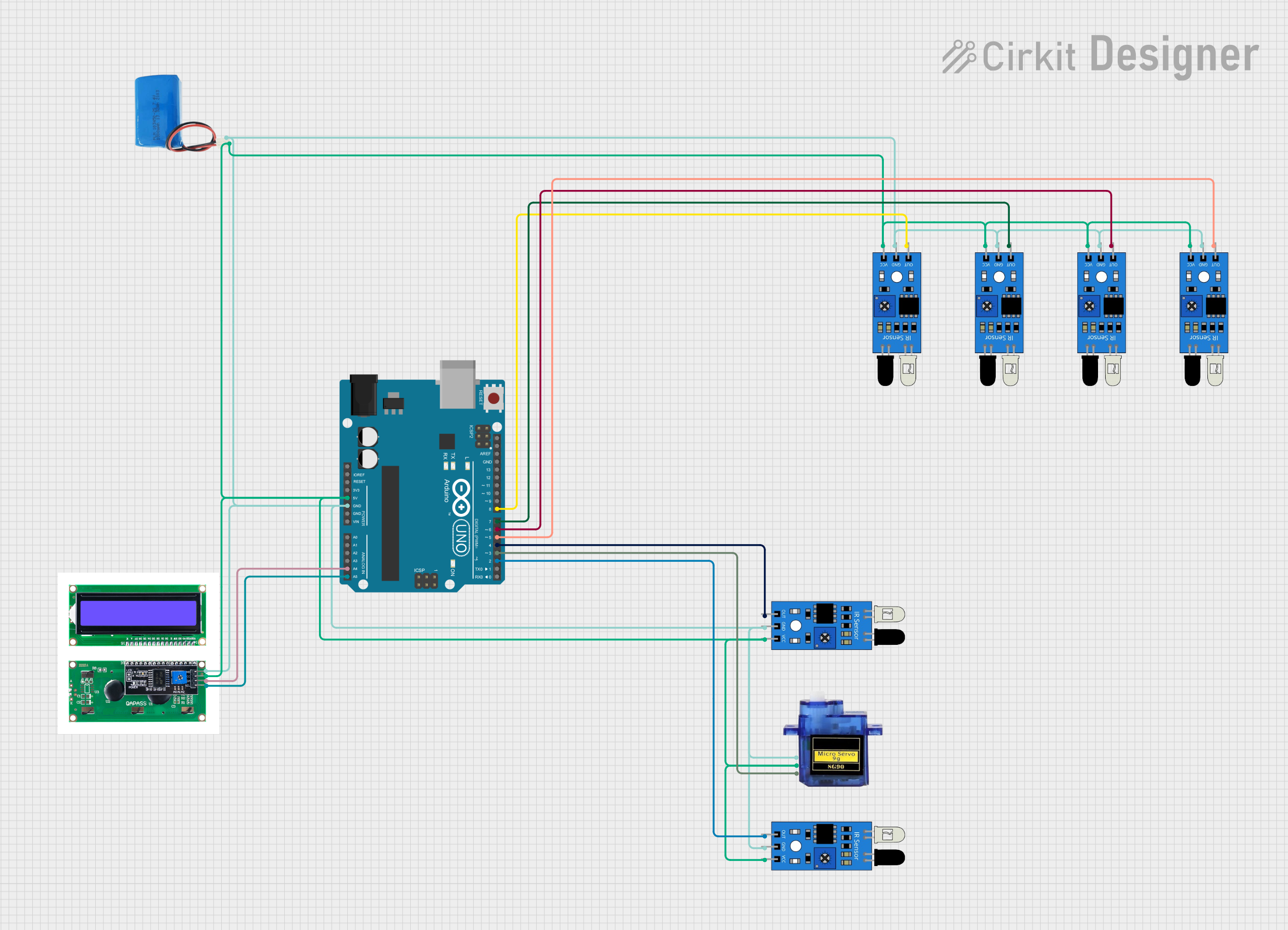
Circuit Documentation
Summary
This circuit consists of multiple IR sensors, an Arduino UNO, an LCD I2C display, a micro servo, and a 5V battery. The IR sensors detect obstacles, the Arduino UNO processes the sensor data, the LCD I2C display shows information, and the micro servo performs mechanical actions based on the sensor inputs. The 5V battery powers the entire circuit.
Component List
IR Sensor
- Description: Infrared sensor used for obstacle detection.
- Pins: out, gnd, vcc
Arduino UNO
- Description: Microcontroller board based on the ATmega328P.
- Pins: UNUSED, IOREF, Reset, 3.3V, 5V, GND, Vin, A0, A1, A2, A3, A4, A5, SCL, SDA, AREF, D13, D12, D11, D10, D9, D8, D7, D6, D5, D4, D3, D2, D1, D0
LCD I2C
- Description: I2C LCD display for showing information.
- Pins: GND, VCC, SDA, SCL
Micro Servo 9G
- Description: Small servo motor for mechanical movements.
- Pins: GND, +5V, PWM
5V Battery
- Description: Power source for the circuit.
- Pins: positive, negative
Wiring Details
IR Sensor
Instance 1:
- out connected to Arduino UNO D8
- gnd connected to 5V battery negative
- vcc connected to 5V battery positive
Instance 2:
- out connected to Arduino UNO D7
- gnd connected to 5V battery negative
- vcc connected to 5V battery positive
Instance 3:
- out connected to Arduino UNO D6
- gnd connected to 5V battery negative
- vcc connected to 5V battery positive
Instance 4:
- out connected to Arduino UNO D5
- gnd connected to 5V battery negative
- vcc connected to 5V battery positive
Instance 5:
- out connected to Arduino UNO D4
- gnd connected to 5V battery negative
- vcc connected to 5V battery positive
Instance 6:
- out connected to Arduino UNO D2
- gnd connected to 5V battery negative
- vcc connected to 5V battery positive
Arduino UNO
- D8 connected to IR Sensor Instance 1 out
- D7 connected to IR Sensor Instance 2 out
- D6 connected to IR Sensor Instance 3 out
- D5 connected to IR Sensor Instance 4 out
- D4 connected to IR Sensor Instance 5 out
- D3 connected to Micro Servo 9G PWM
- D2 connected to IR Sensor Instance 6 out
- A4 connected to LCD I2C SDA
- A5 connected to LCD I2C SCL
- 5V connected to 5V battery positive
- GND connected to 5V battery negative
LCD I2C
- GND connected to 5V battery negative
- VCC connected to 5V battery positive
- SDA connected to Arduino UNO A4
- SCL connected to Arduino UNO A5
Micro Servo 9G
- GND connected to 5V battery negative
- +5V connected to 5V battery positive
- PWM connected to Arduino UNO D3
5V Battery
- positive connected to Arduino UNO 5V, LCD I2C VCC, Micro Servo 9G +5V, IR Sensor vcc pins
- negative connected to Arduino UNO GND, LCD I2C GND, Micro Servo 9G GND, IR Sensor gnd pins
Documented Code
Arduino UNO Code (sketch.ino)
void setup() {
  // put your setup code here, to run once:

}

void loop() {
  // put your main code here, to run repeatedly:

}
This code initializes the Arduino UNO and contains empty setup and loop functions. You can add your specific logic for handling the IR sensors, LCD display, and micro servo in these functions.