
Solar-Powered ESP32 IoT Device with UPS Battery Backup and AC Integration
View and Edit Project In Cirkit Designer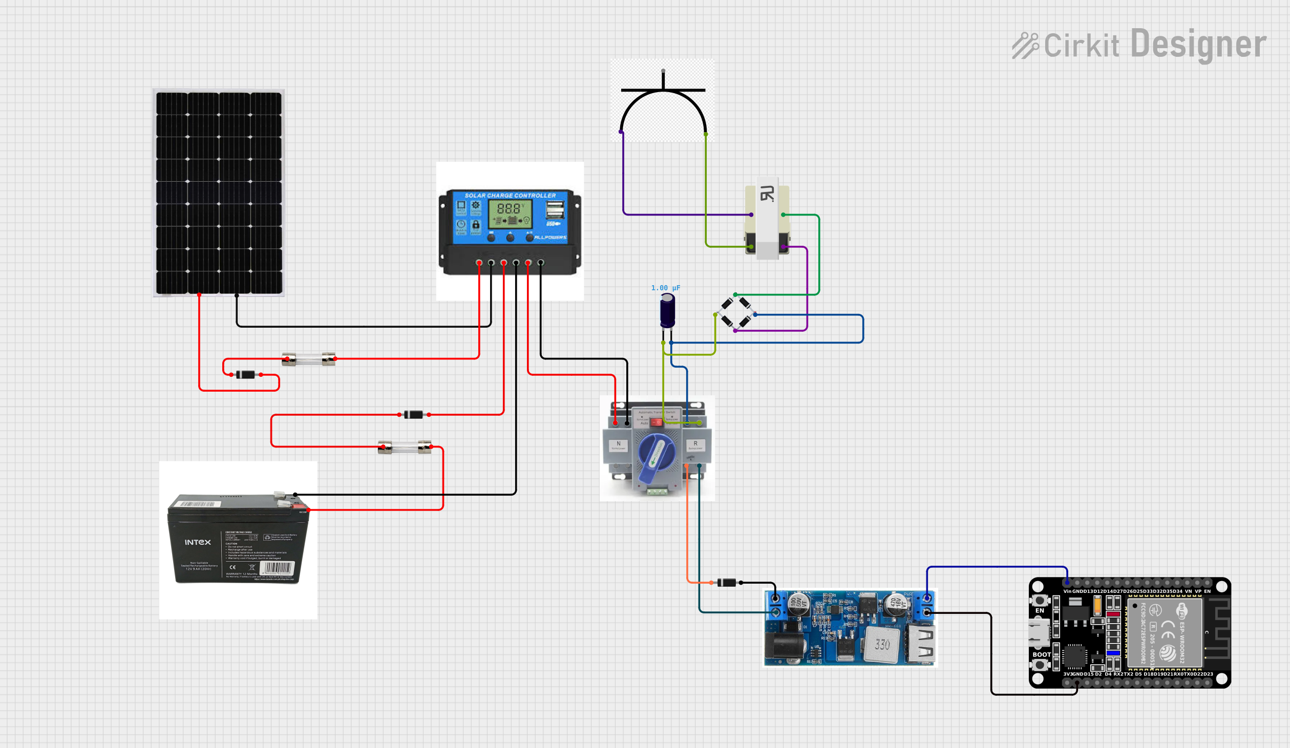
Circuit Documentation
Summary
This circuit is designed to integrate a solar power source with a charge controller, energy storage, and a power conversion system to supply a regulated voltage to an ESP32 microcontroller. The system includes protection elements such as diodes and fuses to ensure safe operation. The ESP32 is programmed to perform tasks as defined in the embedded code, which can be customized according to the specific application needs.
Component List
ESP32 (30 pin)
- A microcontroller with WiFi and Bluetooth capabilities, featuring a variety of digital and analog pins for interfacing with other devices and sensors.
Solar Panel
- A photovoltaic panel that converts sunlight into electrical energy, providing a renewable power source for the circuit.
ATS (Automatic Transfer Switch)
- A device that automatically switches between power sources, typically used for switching between mains power and backup power.
Charge Controller
- A device that regulates the voltage and current coming from the solar panels to charge the battery and prevent overcharging.
Diode (x3)
- Semiconductor devices that allow current to flow in one direction only, used for protection and rectification in the circuit.
UPS BATTERY
- An uninterruptible power supply battery that provides emergency power when the input power source fails.
5A Fuse (x2)
- A safety device that protects the circuit from overcurrent by breaking the connection if the current exceeds 5 amperes.
AC Power Plug
- A connector that allows the circuit to be connected to an AC power source, such as a wall outlet.
24/12v Buck Converter
- A DC-DC converter that steps down the voltage from 24V to a regulated 12V output.
TRANSFORMER
- An electrical device that transfers energy between two or more circuits through electromagnetic induction.
Electrolytic Capacitor
- A capacitor with a capacitance value of 1 microfarad, used for filtering and smoothing the output of the power supply.
Bridge Rectifier
- A circuit that converts AC to DC, consisting of four diodes arranged in a bridge configuration.
Wiring Details
ESP32 (30 pin)
Vinconnected to the 5V output of the 24/12v Buck Converter.GNDconnected to the ground of the 24/12v Buck Converter.
Solar Panel
+connected to the anode of a Diode and through a 5A Fuse to the Solar Positive of the Charge Controller.-connected to the Solar Negative of the Charge Controller.
ATS (Automatic Transfer Switch)
+connected to the Load Positive of the Charge Controller, the anode of a Diode, and the positive of the Electrolytic Capacitor.-connected to the Load Negative of the Charge Controller and the negative of the Electrolytic Capacitor.
Charge Controller
Solar Positiveconnected to the output of a 5A Fuse.Solar Negativeconnected to the negative of the Solar Panel.Battery Positiveconnected to the anode of a Diode.Battery Negativeconnected to the ground of the UPS BATTERY.Load Positiveconnected to the positive of the ATS.Load Negativeconnected to the negative of the ATS.
Diode
- Anode of one Diode connected to the positive of the Solar Panel.
- Cathode of another Diode connected to the Battery Positive of the Charge Controller.
- Anode of the third Diode connected to the VIN+ of the 24/12v Buck Converter.
UPS BATTERY
VCCconnected to the output of a 5A Fuse.GNDconnected to the Battery Negative of the Charge Controller.
5A Fuse
- One 5A Fuse with
inputconnected to the anode of a Diode andoutputconnected to the Solar Positive of the Charge Controller. - Another 5A Fuse with
inputconnected to the cathode of a Diode andoutputconnected to the VCC of the UPS BATTERY.
AC Power Plug
Liveconnected to pin1of the TRANSFORMER.Neutralconnected to pin2of the TRANSFORMER.
24/12v Buck Converter
VIN+connected to the anode of a Diode.VIN-connected to the negative of the ATS.5Vconnected to the Vin of the ESP32.GNDconnected to the ground of the ESP32.
TRANSFORMER
- Pin
1connected to the Live of the AC Power Plug. - Pin
2connected to the Neutral of the AC Power Plug. - Pin
3connected to the source_in+ of the Bridge Rectifier. - Pin
4connected to the Source_in- of the Bridge Rectifier.
Electrolytic Capacitor
+connected to the source_out+ of the Bridge Rectifier and the positive of the ATS.-connected to the source_out- of the Bridge Rectifier and the negative of the ATS.
Bridge Rectifier
Source_in-connected to pin4of the TRANSFORMER.source_in+connected to pin3of the TRANSFORMER.source_out+connected to the positive of the Electrolytic Capacitor.source_out-connected to the negative of the Electrolytic Capacitor.
Documented Code
Microcontroller Code (ESP32)
void setup() {
  // put your setup code here, to run once:

}

void loop() {
  // put your main code here, to run repeatedly:

}
Filename: sketch.ino
Additional Documentation
No additional code documentation provided.
Filename: documentation.txt