
ESP32-Controlled GPS and GSM Tracking System with Relay and Buzzer Notifications
View and Edit Project In Cirkit Designer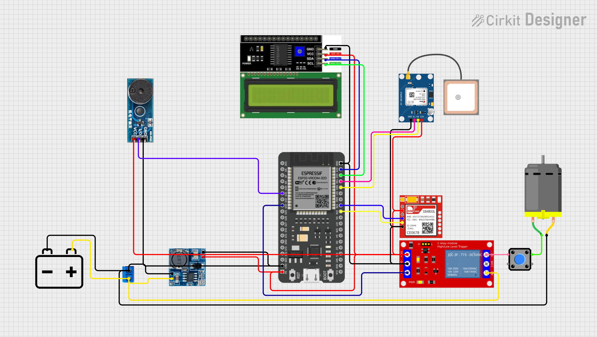
Circuit Documentation
Summary
This circuit is designed to interface various modules with an ESP32 microcontroller. It includes power management through a step-down module, input/output devices such as a buzzer, relay, and pushbutton, communication modules like GPS and GSM, and a display for user interface. The circuit is powered by a 12v battery, which is stepped down to 5V for the logic level components.
Component List
12v Battery
- Description: Provides the main power source for the circuit.
ESP32 - 38 pins
- Description: A microcontroller with WiFi and Bluetooth capabilities, serving as the central processing unit of the circuit.
Step down Module
- Description: Converts the input voltage to a lower voltage level, stepping down from 24V/12V to 5V.
Terminal PCB 2 Pin
- Description: A simple two-pin terminal for connecting external components like the battery and motor.
1 Channel 5V Relay Module
- Description: An electromechanical switch that allows the ESP32 to control high power devices.
Buzzer Module
- Description: An audio signaling device controlled by the ESP32.
LCD I2C Display
- Description: A display module for showing information, interfaced with the ESP32 via I2C.
Sim800l
- Description: A GSM/GPRS module that allows the circuit to communicate over cellular networks.
GPS NEO 6M
- Description: A GPS module for location tracking, interfaced with the ESP32 via serial communication.
DC Motor
- Description: An electric motor that converts electrical energy into mechanical motion.
Pushbutton
- Description: A simple switch that allows user input to the circuit.
Wiring Details
12v Battery
-connected to Terminal PCB 2 Pin (Pin B), Step down Module (GND), and DC Motor (pin 2)+connected to Terminal PCB 2 Pin (Pin A), Step down Module (12v IN+), and 1 Channel 5V Relay Module (N.O.)
ESP32 - 38 pins
G35connected to Buzzer Module (I/O)G33connected to 1 Channel 5V Relay Module (IN)CMDconnected to Step down Module (5v OUT-) and Buzzer Module (GND)5Vconnected to LCD I2C Display (VCC), GPS NEO 6M (VCC), Sim800l (VCC), Step down Module (5v OUT+), 1 Channel 5V Relay Module (VCC+), and Buzzer Module (Vcc)GNDconnected to LCD I2C Display (GND), GPS NEO 6M (GND), Sim800l (GND), and 1 Channel 5V Relay Module (VCC- (GND))G23connected to LCD I2C Display (SDA)G22connected to LCD I2C Display (SCL)TXDconnected to GPS NEO 6M (TX)RXDconnected to GPS NEO 6M (RX)G19connected to Sim800l (RXD)G18connected to Sim800l (TXD)
Step down Module
24v IN+not connectedGNDconnected to 12v Battery (-)12v IN+connected to 12v Battery (+)5v OUT+connected to ESP32 (5V), LCD I2C Display (VCC), GPS NEO 6M (VCC), Sim800l (VCC), 1 Channel 5V Relay Module (VCC+), and Buzzer Module (Vcc)5v OUT-connected to ESP32 (CMD) and Buzzer Module (GND)
Terminal PCB 2 Pin
Pin Aconnected to 12v Battery (+) and 1 Channel 5V Relay Module (N.O.)Pin Bconnected to 12v Battery (-) and DC Motor (pin 2)
1 Channel 5V Relay Module
VCC+connected to Step down Module (5v OUT+)VCC- (GND)connected to ESP32 (GND)INconnected to ESP32 (G33)N.O.connected to 12v Battery (+)COMnot connectedN.C.connected to Pushbutton (Pin 2)
Buzzer Module
GNDconnected to ESP32 (CMD) and Step down Module (5v OUT-)Vccconnected to Step down Module (5v OUT+)I/Oconnected to ESP32 (G35)
LCD I2C Display
GNDconnected to ESP32 (GND)VCCconnected to Step down Module (5v OUT+)SDAconnected to ESP32 (G23)SCLconnected to ESP32 (G22)
Sim800l
NETnot connectedRSTnot connectedVCCconnected to Step down Module (5v OUT+)RXDconnected to ESP32 (G19)TXDconnected to ESP32 (G18)GNDconnected to ESP32 (GND)
GPS NEO 6M
VCCconnected to Step down Module (5v OUT+)RXconnected to ESP32 (RXD)TXconnected to ESP32 (TXD)GNDconnected to ESP32 (GND)
DC Motor
pin 1connected to Pushbutton (Pin 1)pin 2connected to 12v Battery (-) and Terminal PCB 2 Pin (Pin B)
Pushbutton
Pin 1connected to DC Motor (pin 1)Pin 2connected to 1 Channel 5V Relay Module (N.C.)Pin 3not connectedPin 4not connected
Documented Code
sketch.ino
void setup() {
  // put your setup code here, to run once:

}

void loop() {
  // put your main code here, to run repeatedly:

}
documentation.txt
(No additional documentation provided)