
Arduino UNO Based Water Quality Monitoring System with GSM Reporting
View and Edit Project In Cirkit Designer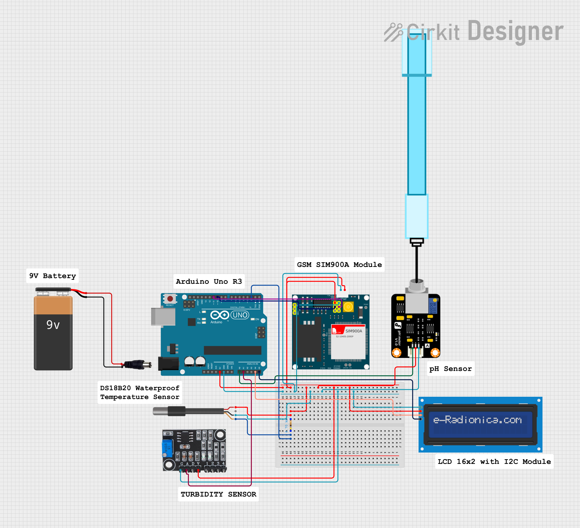
Circuit Documentation
Summary of the Circuit
This circuit is designed to interface various sensors and modules with an Arduino UNO microcontroller. The components include a SIM900A GSM module, a turbidity sensor, a pH meter, a DS18B20 temperature sensor, an LCD screen with I2C interface, and a resistor. The circuit is powered by a 9V battery connected through a power jack. The Arduino UNO serves as the central processing unit, reading sensor data and controlling the LCD display. The SIM900A module allows for GSM communication capabilities.
Component List
Arduino UNO
- Microcontroller board based on the ATmega328P
- It has 14 digital input/output pins, 6 analog inputs, a 16 MHz quartz crystal, a USB connection, a power jack, an ICSP header, and a reset button.
SIM900A
- GSM/GPRS module for communication over the cellular network
- It features a set of GPIOs, including RXD, TXD for UART communication, and status and control pins.
Resistor
- A passive two-terminal electrical component that implements electrical resistance as a circuit element.
- Resistance: 4700 Ohms
Turbidity Module
- Sensor module used to measure the turbidity (cloudiness) of a liquid, indicating the degree to which the water loses its transparency due to the presence of suspended particulates.
PH Meter
- Sensor used to measure the hydrogen-ion activity in water-based solutions, indicating its acidity or alkalinity expressed as pH.
DS18B20 1-Wire Temperature Sensor Probe Cable
- Digital temperature sensor that uses a one-wire interface for communication.
- It provides 9-bit to 12-bit Celsius temperature measurements.
LCD screen 16x2 I2C
- Alphanumeric liquid crystal display capable of displaying 16 characters per line in 2 lines.
- Uses I2C communication protocol.
9V Battery
- Standard 9V battery used to power the circuit.
Power Jack
- A connector for the 9V battery to supply power to the circuit.
Wiring Details
Arduino UNO
5VandGNDare used to power the circuit.- Analog pins
A0andA1are connected to the signal outputs of the pH meter and turbidity module, respectively. - I2C pins
A4(SDA) andA5(SCL) are connected to the corresponding pins on the LCD screen. - Digital pin
D2is connected to the DS18B20 temperature sensor. - Digital pins
D10andD11are used for controlling the SIM900A module.
SIM900A
VCCis connected to the5Voutput from the Arduino.GNDis connected to the ground of the circuit.5VRand5VTare connected to digital pinsD11andD10on the Arduino for communication.
Resistor
- One end is connected to the
D2pin on the Arduino and the other end to theVDDpin of the DS18B20 temperature sensor.
Turbidity Module
VCCis connected to the5Voutput from the Arduino.GNDis connected to the ground of the circuit.AOis connected to theA1analog input on the Arduino.
PH Meter
VCCis connected to the5Voutput from the Arduino.GNDis connected to the ground of the circuit.Signalis connected to theA0analog input on the Arduino.
DS18B20 1-Wire Temperature Sensor Probe Cable
VDDis connected to the5Voutput from the Arduino through a 4700 Ohm resistor.GNDis connected to the ground of the circuit.DQis connected to theD2digital input/output on the Arduino.
LCD screen 16x2 I2C
VCCis connected to the5Voutput from the Arduino.GNDis connected to the ground of the circuit.SDAis connected to theA4analog input on the Arduino.SCLis connected to theA5analog input on the Arduino.
9V Battery and Power Jack
- The
+terminal of the battery is connected to thePOSITIFpin of the power jack. - The
-terminal of the battery is connected to theNEGATIFpin of the power jack.
Documented Code
Arduino UNO Code (sketch.ino)
void setup() {
  // put your setup code here, to run once:

}

void loop() {
  // put your main code here, to run repeatedly:

}
Note: The provided code is a template and does not contain any functional code. It needs to be populated with the logic for reading sensors, controlling the LCD, and handling communication with the SIM900A module.