
Arduino Mega and UNO-Based Multi-Sensor Environmental Monitoring System with GPS
View and Edit Project In Cirkit Designer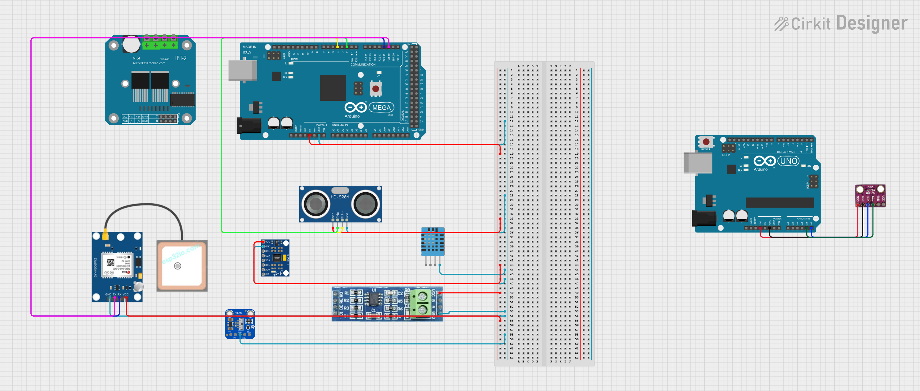
Circuit Documentation
Summary
This document provides a detailed overview of a circuit that includes an Arduino Mega 2560, an Arduino UNO, various sensors, and a motor driver. The circuit is designed to interface multiple sensors and modules with the microcontrollers to perform various tasks such as distance measurement, temperature and humidity sensing, GPS tracking, and motor control.
Component List
Arduino Mega 2560
- Description: A microcontroller board based on the ATmega2560.
- Pins: IOREF, RESET, 3V3, 5V, GND, VIN, A0-A15, D21/SCL, D20/SDA, D19/RX1, D18/TX1, D17 PWM/RX2, D16 PWM/TX2, D15/RX3, D14/TX3, D0 RX0, D1 TX0, D2 PWM, D3 PWM, D4 PWM, D5 PWM, D6 PWM, D7 PWM, D8 PWM, D9 PWM, D10 PWM, D11 PWM, D12 PWM, D13 PWM, AREF, SDA, SCL, D52, D50, D48, D46, D44, D42, D40, D38, D36, D34, D32, D30, D28, D26, D24, D22, D53, D51, D49, D47, D45, D43, D41, D39, D37, D35, D33, D31, D29, D27, D25, D23, 6swdw.
HC-SR04 Ultrasonic Sensor
- Description: A sensor used for distance measurement.
- Pins: VCC, TRIG, ECHO, GND.
BTS7960 Motor Driver
- Description: A high-current motor driver.
- Pins: Pin 1, Pin 2, Pin 3, Pin 4, Pin 5, Pin 6, Pin 7, Pin 8, Pin 9, Pin 10, Pin 11, Pin 12.
BMP280
- Description: A barometric pressure sensor.
- Pins: SDO, CSB, SDA, SCL, GND, VCC.
NEO-6M (GPS MODULE)
- Description: A GPS module for location tracking.
- Pins: GND, TX, RX, VCC.
InvenSense MPU6050
- Description: A 6-axis motion tracking device.
- Pins: VCC, GND, SCL, SDA, XDA, XCL, AD0, INT.
RS485
- Description: A communication module for RS485 protocol.
- Pins: VCC, RO, RE, GND, B, A, DE, DI.
Adafruit VEML7700
- Description: A light sensor.
- Pins: VIN, 3.3V, GND, SCL, SDA.
DHT11 Humidity and Temperature Sensor
- Description: A sensor for measuring humidity and temperature.
- Pins: VDD, DATA, NULL, GND.
Arduino UNO
- Description: A microcontroller board based on the ATmega328P.
- Pins: UNUSED, IOREF, Reset, 3.3V, 5V, GND, Vin, A0-A5, SCL, SDA, AREF, D13, D12, D11, D10, D9, D8, D7, D6, D5, D4, D3, D2, D1, D0.
Wiring Details
Arduino Mega 2560
GND connected to:
- HC-SR04 Ultrasonic Sensor (GND)
- DHT11 Humidity and Temperature Sensor (GND)
- InvenSense MPU6050 (GND)
- RS485 (GND)
- NEO-6M (GPS MODULE) (GND)
- Adafruit VEML7700 (GND)
5V connected to:
- HC-SR04 Ultrasonic Sensor (VCC)
- InvenSense MPU6050 (VCC)
- RS485 (VCC)
- NEO-6M (GPS MODULE) (VCC)
D19/RX1 connected to:
- NEO-6M (GPS MODULE) (TX)
D18/TX1 connected to:
- NEO-6M (GPS MODULE) (RX)
D2 PWM connected to:
- HC-SR04 Ultrasonic Sensor (TRIG)
D4 PWM connected to:
- HC-SR04 Ultrasonic Sensor (ECHO)
HC-SR04 Ultrasonic Sensor
GND connected to:
- Arduino Mega 2560 (GND)
VCC connected to:
- Arduino Mega 2560 (5V)
TRIG connected to:
- Arduino Mega 2560 (D2 PWM)
ECHO connected to:
- Arduino Mega 2560 (D4 PWM)
BMP280
SDO connected to:
- Arduino UNO (3.3V)
CSB connected to:
- Arduino UNO (GND)
SDA connected to:
- Arduino UNO (A5)
SCL connected to:
- Arduino UNO (A4)
NEO-6M (GPS MODULE)
GND connected to:
- Arduino Mega 2560 (GND)
TX connected to:
- Arduino Mega 2560 (D19/RX1)
RX connected to:
- Arduino Mega 2560 (D18/TX1)
VCC connected to:
- Arduino Mega 2560 (5V)
InvenSense MPU6050
GND connected to:
- Arduino Mega 2560 (GND)
VCC connected to:
- Arduino Mega 2560 (5V)
RS485
GND connected to:
- Arduino Mega 2560 (GND)
VCC connected to:
- Arduino Mega 2560 (5V)
Adafruit VEML7700
- GND connected to:
- Arduino Mega 2560 (GND)
DHT11 Humidity and Temperature Sensor
- GND connected to:
- Arduino Mega 2560 (GND)
Arduino UNO
3.3V connected to:
- BMP280 (SDO)
GND connected to:
- BMP280 (CSB)
A5 connected to:
- BMP280 (SDA)
A4 connected to:
- BMP280 (SCL)
Documented Code
Arduino Mega 2560 Code
void setup() {
  // put your setup code here, to run once:

}

void loop() {
  // put your main code here, to run repeatedly:

}
Arduino UNO Code
void setup() {
  // put your setup code here, to run once:

}

void loop() {
  // put your main code here, to run repeatedly:

}
This documentation provides a comprehensive overview of the circuit, including the components used, their connections, and the code running on the microcontrollers.