
Arduino and ESP32-Based Smart Home Monitoring System with GSM and Battery Backup
View and Edit Project In Cirkit Designer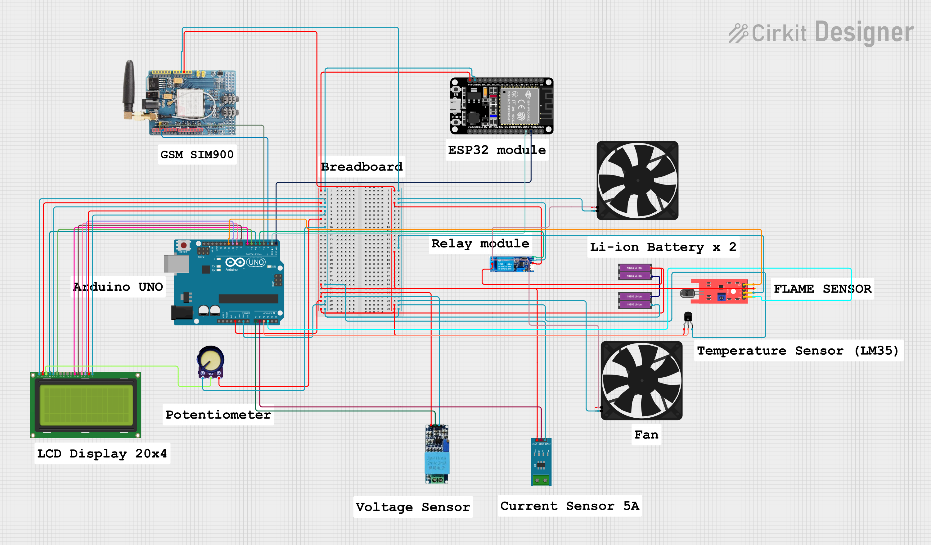
Circuit Documentation
Summary
This circuit integrates various sensors and modules with an Arduino UNO and an ESP32 microcontroller. The system includes voltage, current, temperature, and flame sensors, a GSM module, a relay module, and an LCD display. The circuit is designed to monitor environmental parameters and control a fan based on sensor inputs.
Component List
Arduino UNO
- Description: A microcontroller board based on the ATmega328P.
- Pins: UNUSED, IOREF, Reset, 3.3V, 5V, GND, Vin, A0, A1, A2, A3, A4, A5, SCL, SDA, AREF, D13, D12, D11, D10, D9, D8, D7, D6, D5, D4, D3, D2, D1, D0
Voltage Sensor
- Description: Measures voltage levels.
- Pins: Ground, Phase, Vcc, Out, Gnd
Current Sensor 5A
- Description: Measures current up to 5A.
- Pins: 1, 2, GND, OUT, VCC
Temperature Sensor (LM35)
- Description: Measures temperature.
- Pins: +Vs, Vout, GND
ESP32 (30 pin)
- Description: A low-power system on a chip microcontroller with integrated Wi-Fi and dual-mode Bluetooth.
- Pins: EN, VP, VN, D34, D35, D32, D33, D25, D26, D27, D14, D12, D13, GND, Vin, D23, D22, TX0, RX0, D21, D19, D18, D5, TX2, RX2, D4, D2, D15, 3V3
GSM SIM900
- Description: A GSM module for communication.
- Pins: A5, A4, A3, A2, A1, A0, 5V, GND, 3.3V, RESET, D0, D1, D2, D3, D4, D5, D6, D7, D8, D9, D10, D11, D12, D13, AREF
Relay module 5v-30v
- Description: A relay module for switching.
- Pins: common contact, normally open, normally closed, trigger, V-, V+
Fan
- Description: A fan for cooling.
- Pins: GND, 5V
18650 Li-ion Battery x 2
- Description: Power source.
- Pins: +, -
Potentiometer
- Description: A variable resistor.
- Pins: GND, Output, VCC
LCD Display 20x4
- Description: A 20x4 character LCD display.
- Pins: LEDK, LEDA, DB7, DB6, DB5, DB4, DB3, DB2, DB1, DB0, E, RW, RS, VO, VDD, VSS
KY-026 Flame Sensor
- Description: Detects flame.
- Pins: A0, GND, VCC, D0
Wiring Details
Arduino UNO
- 5V: Connected to Vcc of Voltage Sensor, Current Sensor 5A, Potentiometer, Relay module, GSM SIM900, KY-026 Flame Sensor, and +Vs of Temperature Sensor (LM35).
- GND: Connected to Gnd of Voltage Sensor, GND of Current Sensor 5A, Potentiometer, Relay module, GSM SIM900, KY-026 Flame Sensor, and GND of Temperature Sensor (LM35).
- A0: Connected to Out of Voltage Sensor.
- A1: Connected to OUT of Current Sensor 5A.
- A2: Connected to Vout of Temperature Sensor (LM35).
- A3: Connected to A0 of KY-026 Flame Sensor.
- D11: Connected to D0 of KY-026 Flame Sensor.
- D10: Connected to DB7 of LCD Display.
- D9: Connected to DB6 of LCD Display.
- D8: Connected to DB5 of LCD Display.
- D7: Connected to DB4 of LCD Display.
- D6: Connected to E of LCD Display.
- D5: Connected to RS of LCD Display.
- D4: Connected to trigger of Relay module.
- D3: Connected to D2 of GSM SIM900.
- D2: Connected to D3 of GSM SIM900.
- D1: Connected to RX0 of ESP32.
- D0: Connected to TX0 of ESP32.
ESP32 (30 pin)
- Vin: Connected to VDD and LEDA of LCD Display, VCC of Potentiometer, VCC of Current Sensor 5A, Vcc of Voltage Sensor, 5V of Arduino UNO, common contact and V+ of Relay module, + of 18650 Li-ion Battery, 5V of GSM SIM900, VCC of KY-026 Flame Sensor, and +Vs of Temperature Sensor (LM35).
- GND: Connected to VSS, RW, and LEDK of LCD Display, GND of Potentiometer, GND of Current Sensor 5A, Gnd of Voltage Sensor, GND of Arduino UNO, - of 18650 Li-ion Battery, GND of GSM SIM900, GND of Fan, V- of Relay module, GND of KY-026 Flame Sensor, and GND of Temperature Sensor (LM35).
Voltage Sensor
- Out: Connected to A0 of Arduino UNO.
Current Sensor 5A
- OUT: Connected to A1 of Arduino UNO.
Temperature Sensor (LM35)
- Vout: Connected to A2 of Arduino UNO.
KY-026 Flame Sensor
- A0: Connected to A3 of Arduino UNO.
- D0: Connected to D11 of Arduino UNO.
LCD Display 20x4
- DB7: Connected to D10 of Arduino UNO.
- DB6: Connected to D9 of Arduino UNO.
- DB5: Connected to D8 of Arduino UNO.
- DB4: Connected to D7 of Arduino UNO.
- E: Connected to D6 of Arduino UNO.
- RS: Connected to D5 of Arduino UNO.
- VO: Connected to Output of Potentiometer.
Relay module 5v-30v
- trigger: Connected to D4 of Arduino UNO.
- normally open: Connected to 5V of Fan.
GSM SIM900
- D2: Connected to D3 of Arduino UNO.
- D3: Connected to D2 of Arduino UNO.
Fan
- 5V: Connected to normally open of Relay module.
18650 Li-ion Battery x 2
- +: Connected to - of the other 18650 Li-ion Battery.
Documented Code
Arduino UNO Code
void setup() {
  // put your setup code here, to run once:

}

void loop() {
  // put your main code here, to run repeatedly:

}
Additional Documentation
// No additional documentation provided.
This documentation provides a comprehensive overview of the circuit, including a summary, detailed component list, wiring details, and the code used in the microcontroller.