
Arduino-Controlled Load Cell Measurement System with Relay-Activated Indicator Lamps
View and Edit Project In Cirkit Designer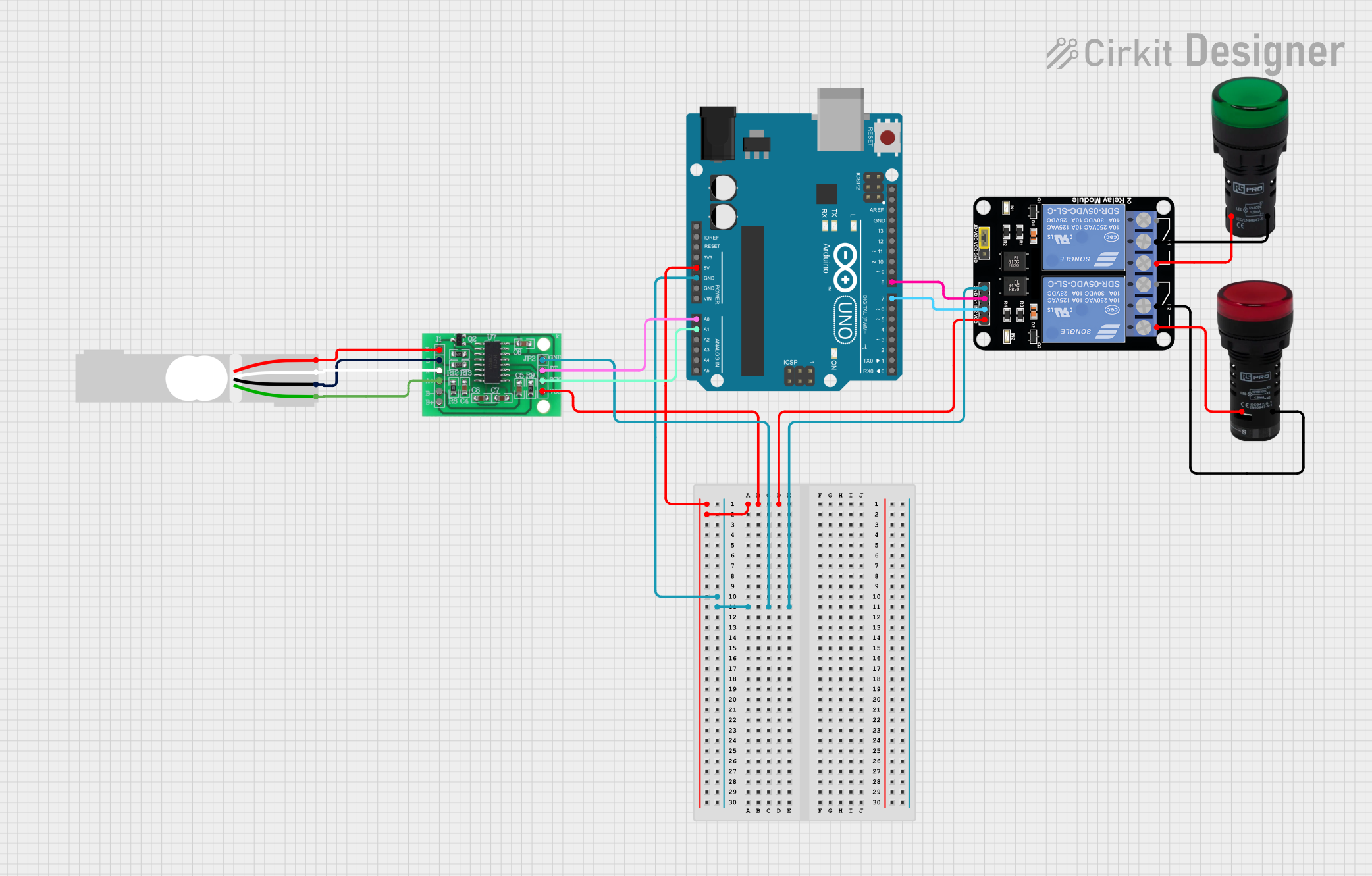
Circuit Documentation
Summary of the Circuit
This circuit is designed to interface a load cell with an Arduino UNO microcontroller through an HX711 bridge sensor interface. The Arduino UNO controls a 2-channel relay module which in turn controls two pilot lamps (one green and one red). The HX711 is used to amplify and convert the load cell signals for the Arduino to process. The relay module is used to indicate the status or outcome of the process, with the green lamp indicating a successful operation and the red lamp indicating a failure or alert condition.
Component List
HX711 - Bridge Sensor Interface
- Description: A precision 24-bit analog-to-digital converter (ADC) designed for weigh scales and industrial control applications to interface directly with a bridge sensor.
- Pins: E+, E-, A-, A+, B-, B+, GND, DATA (OUT), SCK (CLOCK IN), 3.3/3.5V Supply
Load Cell - Red/white/black/green
- Description: A transducer that converts force into an electrical signal.
- Pins: E+, A-, E-, A+
Pilot Lamp Green
- Description: An indicator light that illuminates green.
- Pins: X1, X2
Pilot Lamp Red
- Description: An indicator light that illuminates red.
- Pins: X1, X2
Relay Module 2 Channel
- Description: A module with two independent relays that can control high power devices.
- Pins: GND, IN1, IN2, VCC, NC1, COM, NO1, NC2, NO2
Arduino UNO
- Description: A microcontroller board based on the ATmega328P.
- Pins: UNUSED, IOREF, Reset, 3.3V, 5V, GND, Vin, A0-A5, SCL, SDA, AREF, D13-D0
Wiring Details
HX711 - Bridge Sensor Interface
- 3.3/3.5V Supply connected to 5V of Arduino UNO and VCC of Relay Module 2 Channel
- GND - GROUND connected to GND of Arduino UNO and GND of Relay Module 2 Channel
- DATA (OUT) connected to A0 of Arduino UNO
- SCK - CLOCK (IN) connected to A1 of Arduino UNO
- E+ connected to E+ of Load Cell
- E- connected to E- of Load Cell
- A- connected to A- of Load Cell
- A+ connected to A+ of Load Cell
Load Cell - Red/white/black/green
- E+ connected to E+ of HX711
- A- connected to A- of HX711
- E- connected to E- of HX711
- A+ connected to A+ of HX711
Pilot Lamp Green
- X1 connected to NO1 of Relay Module 2 Channel
- X2 connected to COM of Relay Module 2 Channel
Pilot Lamp Red
- X1 connected to NO2 of Relay Module 2 Channel
- X2 connected to COM of Relay Module 2 Channel
Relay Module 2 Channel
- VCC connected to 5V of Arduino UNO
- GND connected to GND of Arduino UNO
- IN1 connected to D8 of Arduino UNO
- IN2 connected to D7 of Arduino UNO
- NO1 connected to X1 of Pilot Lamp Green
- COM connected to X2 of Pilot Lamp Green and X2 of Pilot Lamp Red
- NO2 connected to X1 of Pilot Lamp Red
Documented Code
Arduino UNO Code (sketch.ino)
void setup() {
  // put your setup code here, to run once:

}

void loop() {
  // put your main code here, to run repeatedly:

}
Note: The provided code is a template and does not contain any functional code. It needs to be populated with the logic to interact with the HX711 and control the relay module based on the load cell's readings.