
Arduino Nano and PCA9685 PWM Servo Controller for Multi-Servo Robotic Arm
View and Edit Project In Cirkit Designer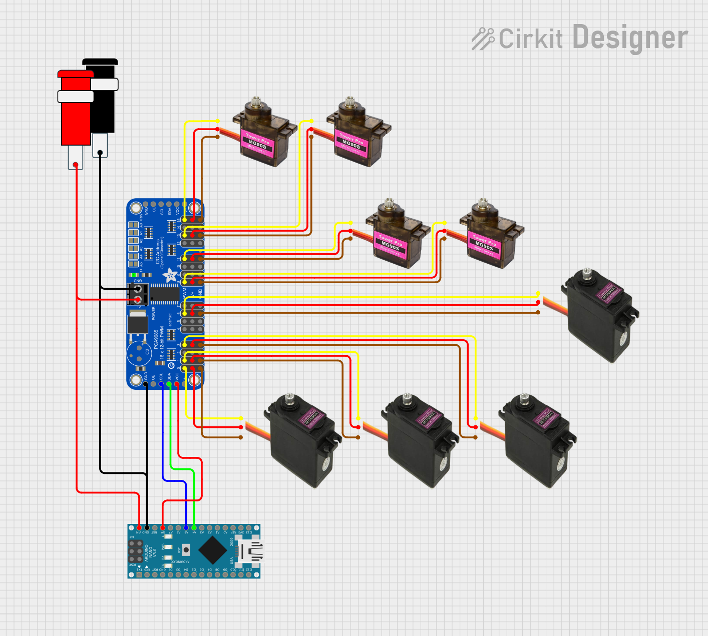
Circuit Documentation
Summary
This circuit is designed to control multiple servos using an Arduino Nano and an Adafruit PCA9685 PWM Servo Breakout. The servos are powered and controlled through the PWM signals generated by the PCA9685, which is in turn controlled by the Arduino Nano via I2C communication. The circuit is powered by a 5V power supply.
Component List
Adafruit PCA9685 PWM Servo Breakout
- Description: A 16-channel PWM driver that can control up to 16 servos or LEDs.
- Pins: 5.0V, GND, PWRIN, PWM0-PWM15, VCC, SDA, SCL, OE
MG90S Servo Motor
- Description: A small servo motor commonly used in robotics.
- Pins: GND, VCC, SIGNAL
MG996R Servo Motor
- Description: A high-torque servo motor suitable for larger robotic applications.
- Pins: SIGNAL, VCC, GND
Connector 5V
- Description: A connector providing 5V power supply.
- Pins: GND, VCC
Arduino Nano
- Description: A small, complete, and breadboard-friendly microcontroller board based on the ATmega328P.
- Pins: D1/TX, D0/RX, RESET, GND, D2-D13, VIN, 5V, A0-A7, AREF, 3V3
Wiring Details
Adafruit PCA9685 PWM Servo Breakout
- 5.0V connected to VCC of MG996R, MG90S, and 5.0V of Arduino Nano.
- GND connected to GND of MG996R, MG90S, and GND of Arduino Nano.
- PWRIN connected to VCC of Connector 5V.
- SDA connected to A4 of Arduino Nano.
- SCL connected to A5 of Arduino Nano.
- PWM0 connected to SIGNAL of MG996R.
- PWM1 connected to SIGNAL of MG996R.
- PWM3 connected to SIGNAL of MG996R.
- PWM6 connected to SIGNAL of MG996R.
- PWM8 connected to SIGNAL of MG90S.
- PWM11 connected to SIGNAL of MG90S.
- PWM13 connected to SIGNAL of MG90S.
- PWM15 connected to SIGNAL of MG90S.
MG90S Servo Motor
- GND connected to GND of Adafruit PCA9685 PWM Servo Breakout.
- VCC connected to 5.0V of Adafruit PCA9685 PWM Servo Breakout.
- SIGNAL connected to PWM15, PWM13, PWM11, PWM8 of Adafruit PCA9685 PWM Servo Breakout.
MG996R Servo Motor
- GND connected to GND of Adafruit PCA9685 PWM Servo Breakout.
- VCC connected to 5.0V of Adafruit PCA9685 PWM Servo Breakout.
- SIGNAL connected to PWM0, PWM1, PWM3, PWM6 of Adafruit PCA9685 PWM Servo Breakout.
Connector 5V
- GND connected to GND of Adafruit PCA9685 PWM Servo Breakout and Arduino Nano.
- VCC connected to PWRIN of Adafruit PCA9685 PWM Servo Breakout and VIN of Arduino Nano.
Arduino Nano
- 5V connected to VCC of Adafruit PCA9685 PWM Servo Breakout.
- GND connected to GND of Adafruit PCA9685 PWM Servo Breakout and Connector 5V.
- VIN connected to VCC of Connector 5V.
- A4 connected to SDA of Adafruit PCA9685 PWM Servo Breakout.
- A5 connected to SCL of Adafruit PCA9685 PWM Servo Breakout.
Documented Code
Arduino Nano Code (sketch.ino)
void setup() {
  // put your setup code here, to run once:

}

void loop() {
  // put your main code here, to run repeatedly:

}
Additional Documentation (documentation.txt)
This documentation provides a comprehensive overview of the circuit, including a summary, detailed component list, wiring details, and the code used in the Arduino Nano.