
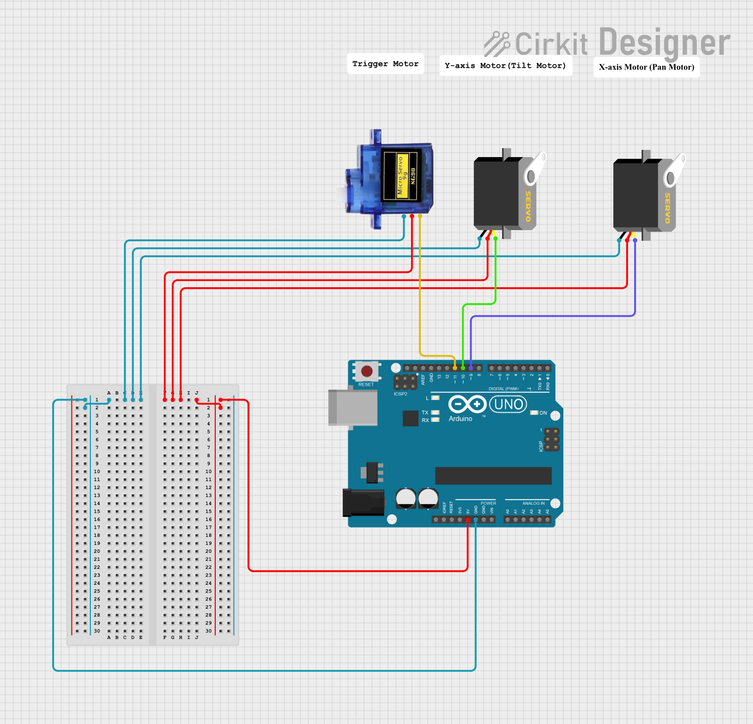
Circuit Documentation
Summary of the Circuit
This circuit is designed to control multiple servo motors using an Arduino UNO microcontroller. The circuit includes two standard servos and one micro servo 9G, all of which are powered by the Arduino's 5V output and share a common ground. The servos are controlled by PWM signals from the Arduino's digital pins.
Component List
Servo (2x)
- Pins: gnd, vcc, pulse
- Description: A standard servo motor that rotates from 0 to 180 degrees based on the PWM signal applied to the pulse pin.
Micro servo 9G
- Pins: GND, +5V, PWM
- Description: A smaller servo motor similar to the standard servo, typically used for lighter and smaller applications.
Arduino UNO
- Pins: UNUSED, IOREF, Reset, 3.3V, 5V, GND, Vin, A0-A5, SCL, SDA, AREF, D0-D13
- Description: A microcontroller board based on the ATmega328P, with digital and analog I/O pins.
Comment (3x)
- Pins: N/A
- Description: Placeholder for comments or notes within the circuit design, not a physical component.
Wiring Details
Servo 1
- Ground: Connected to Arduino UNO GND
- VCC: Connected to Arduino UNO 5V
- Pulse: Connected to Arduino UNO Digital Pin D10
Servo 2
- Ground: Connected to Arduino UNO GND
- VCC: Connected to Arduino UNO 5V
- Pulse: Connected to Arduino UNO Digital Pin D9
Micro servo 9G
- Ground: Connected to Arduino UNO GND
- +5V: Connected to Arduino UNO 5V
- PWM: Connected to Arduino UNO Digital Pin D11
Documented Code
Arduino UNO Code (sketch.ino)
void setup() {
  // put your setup code here, to run once:

}

void loop() {
  // put your main code here, to run repeatedly:

}
This is the basic structure of an Arduino sketch, with two primary functions: setup() and loop(). The setup() function is called once when the sketch starts and is used to initialize settings or pin modes. The loop() function is called repeatedly and contains the main logic of the sketch.
The provided code is a template and does not contain any specific instructions for controlling the servos. To control the servos, PWM signals need to be generated and sent to the corresponding pins connected to the servo pulse inputs. This can be done using the analogWrite() function for PWM-capable pins on the Arduino UNO.
Note: The actual implementation code for controlling the servos is not provided in the input and would need to be added to the setup() and loop() functions as required by the specific application.