Arduino Nano Ultrasonic Distance Sensor with Buzzer Alert - Battery Powered
Circuit Documentation
Summary
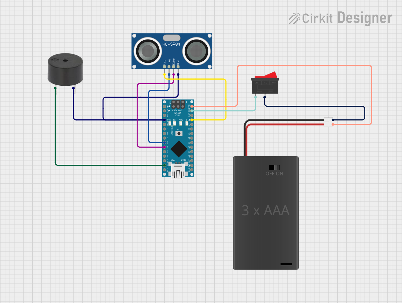
This circuit is designed to interface an Arduino Nano with an HC-SR04 Ultrasonic Sensor and a buzzer. The circuit is powered by a 3xAAA battery pack with a rocker switch for power control. The Arduino Nano reads distance measurements from the ultrasonic sensor and can trigger the buzzer based on the readings.
Component List
Arduino Nano
- Description: A small, complete, and breadboard-friendly board based on the ATmega328P.
- Pins: D1/TX, D0/RX, RESET, GND, D2, D3, D4, D5, D6, D7, D8, D9, D10, D11/MOSI, D12/MISO, VIN, 5V, A7, A6, A5, A4, A3, A2, A1, A0, AREF, 3V3, D13/SCK
Rocker Switch
- Description: A simple on/off switch to control the power supply.
- Pins: 1, 2
3xAAA Battery Pack with Switch and JST
- Description: A battery pack that holds three AAA batteries and includes a switch and JST connector.
- Pins: POS, NEG
Buzzer
- Description: An electronic device that produces a sound when a voltage is applied.
- Pins: PIN, GND
HC-SR04 Ultrasonic Sensor
- Description: A sensor that measures distance by using ultrasonic waves.
- Pins: VCC, TRIG, ECHO, GND
Wiring Details
Arduino Nano
GND is connected to:
- GND of the Buzzer
- GND of the HC-SR04 Ultrasonic Sensor
- Pin 1 of the Rocker Switch
D6 is connected to:
- TRIG of the HC-SR04 Ultrasonic Sensor
D7 is connected to:
- ECHO of the HC-SR04 Ultrasonic Sensor
D11/MOSI is connected to:
- PIN of the Buzzer
VIN is connected to:
- POS of the 3xAAA Battery Pack with Switch and JST
5V is connected to:
- VCC of the HC-SR04 Ultrasonic Sensor
Rocker Switch
Pin 1 is connected to:
- GND of the Arduino Nano
Pin 2 is connected to:
- NEG of the 3xAAA Battery Pack with Switch and JST
3xAAA Battery Pack with Switch and JST
POS is connected to:
- VIN of the Arduino Nano
NEG is connected to:
- Pin 2 of the Rocker Switch
Buzzer
PIN is connected to:
- D11/MOSI of the Arduino Nano
GND is connected to:
- GND of the Arduino Nano
HC-SR04 Ultrasonic Sensor
VCC is connected to:
- 5V of the Arduino Nano
TRIG is connected to:
- D6 of the Arduino Nano
ECHO is connected to:
- D7 of the Arduino Nano
GND is connected to:
- GND of the Arduino Nano
Documented Code
Arduino Nano Code (sketch.ino)
void setup() {
  // put your setup code here, to run once:

}

void loop() {
  // put your main code here, to run repeatedly:

}
Additional Documentation (documentation.txt)
This documentation provides a comprehensive overview of the circuit, including a summary, detailed component list, wiring details, and the code used in the Arduino Nano.