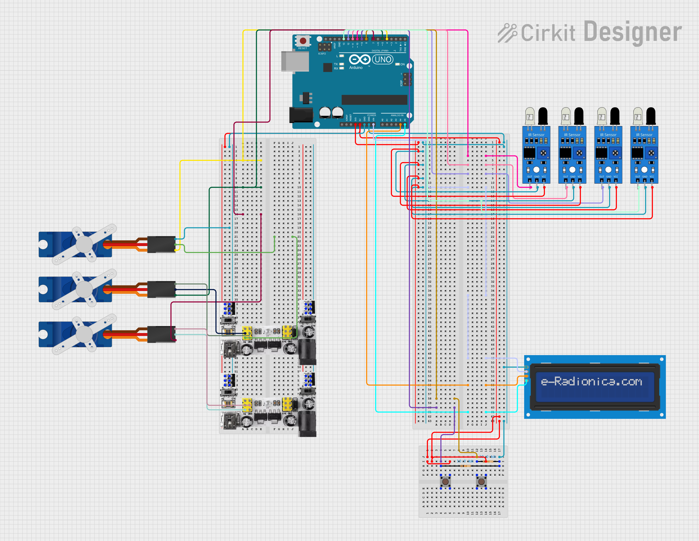
Arduino UNO Controlled Servo and IR Sensor Interaction System

Circuit Documentation
Summary
This circuit integrates various components controlled by an Arduino UNO microcontroller. It includes input devices such as pushbuttons and IR sensors, output devices like servos and an LCD screen, and power management modules. The circuit is designed to interact with the environment through the IR sensors and respond to user inputs via pushbuttons, displaying information on the LCD and actuating movements with the servos.
Component List
Microcontroller
- Arduino UNO: A microcontroller board based on the ATmega328P. It has digital input/output pins, analog inputs, a USB connection for programming, and power jacks.
Input Devices
- Pushbutton: A simple switch mechanism for controlling some aspect of a machine or a process. Buttons are typically made out of hard material, usually plastic or metal.
- IR Sensor: An electronic device that emits and/or detects infrared radiation to sense some aspect of its surroundings.
Output Devices
- Tower Pro SG90 Servo: A small and lightweight servo motor capable of precise control. It can rotate approximately 180 degrees and works on a PWM signal.
- LCD Screen 16x2 I2C: A liquid crystal display capable of displaying 16 characters per line and 2 lines. It uses the I2C protocol for communication, which reduces the number of pins needed for operation.
Power Management
- Breadboard Power Module (3.3/5V): A module that provides both 3.3V and 5V power supply outputs, suitable for breadboard power supply needs.
Passive Components
- Resistor: A passive two-terminal electrical component that implements electrical resistance as a circuit element. In this circuit, 10kΩ resistors are used, possibly for pull-up or pull-down configurations.
Wiring Details
Arduino UNO
- Digital pins D4, D5, D7, D8, D9, D10, D11, D12, and D13 are used to interface with servos and IR sensors.
- Analog pins A4 and A5 are connected to the SDA and SCL pins of the LCD screen for I2C communication.
- Power pins 3.3V and 5V provide power to the IR sensors and pushbuttons, respectively.
- GND pins are used to complete the circuits for the IR sensors, pushbuttons, servos, and LCD screen.
Pushbuttons
- Connected to digital pins D8 and D9 on the Arduino UNO for input detection.
- Wired with 10kΩ resistors, likely for pull-up or pull-down configurations.
- 5V power from the Arduino UNO is supplied to the pushbuttons.
IR Sensors
- Output pins connected to digital pins D10, D11, D12, and D13 on the Arduino UNO for signal detection.
- GND pins connected to the Arduino UNO's GND.
- VCC pins powered by the Arduino UNO's 3.3V output.
Tower Pro SG90 Servos
- Signal pins connected to digital pins D4, D5, and D7 on the Arduino UNO for PWM control signals.
- +5V and GND pins connected to the Breadboard Power Module to provide power.
LCD Screen 16x2 I2C
- SDA and SCL pins connected to analog pins A4 and A5 on the Arduino UNO for I2C communication.
- VCC pin connected to the Arduino UNO's Vin for power.
- GND pin connected to the Arduino UNO's GND.
Breadboard Power Module (3.3/5V)
- Provides +5V and GND to the servos.
- Also supplies power to the pushbuttons and completes the GND connections for various components.
Resistor
- Two 10kΩ resistors are used, likely for pull-up or pull-down configurations with the pushbuttons.
Documented Code
Arduino UNO Code (sketch.ino)
void setup() {
  // put your setup code here, to run once:

}

void loop() {
  // put your main code here, to run repeatedly:

}
This code template is the starting point for the Arduino sketch. The setup() function is called once when the program starts and is used to initialize the settings. The loop() function runs repeatedly, allowing the microcontroller to perform operations based on the inputs from sensors and buttons, control the servos, and update the display on the LCD screen. The actual implementation details would be added to these functions based on the specific requirements of the circuit's operation.