
Multi-Rate LED Flasher Circuit with 555 Timers and 12V Battery
View and Edit Project In Cirkit Designer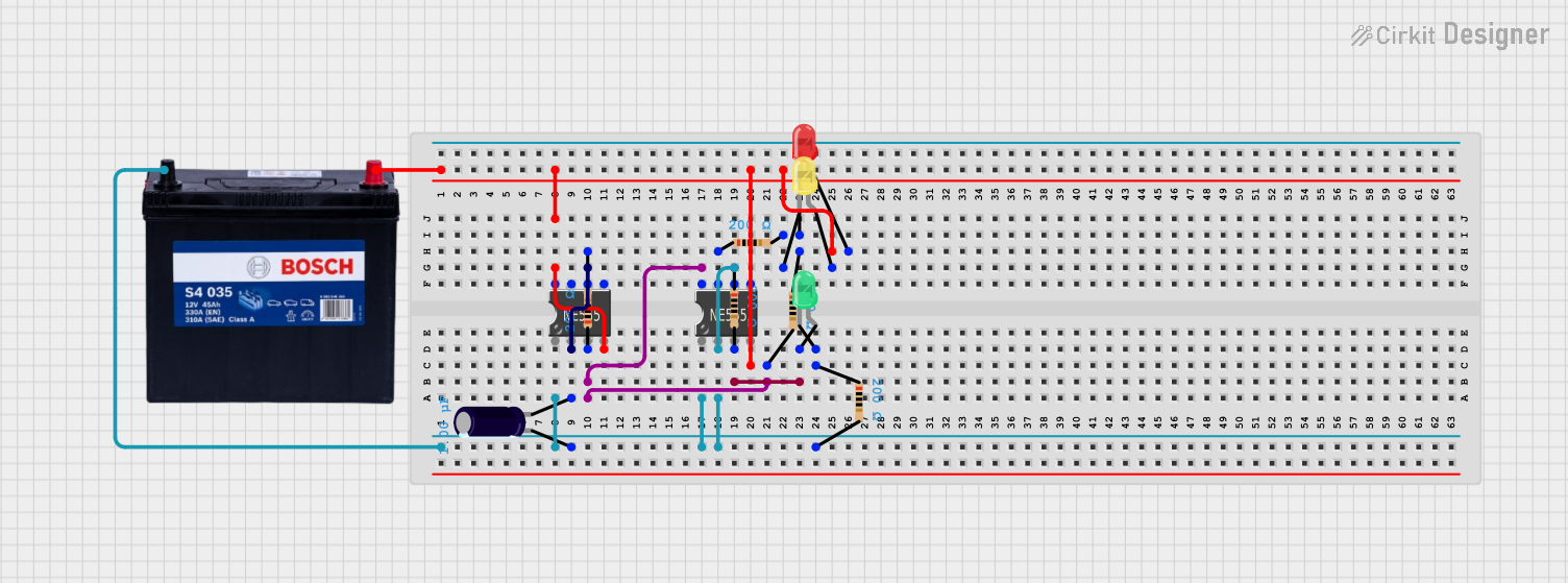
Circuit Documentation
Summary of the Circuit
This circuit appears to be a timer or oscillator circuit utilizing two 555 Timer ICs. The circuit is powered by a 12V 200Ah battery and includes several resistors and LEDs of different colors (red, yellow, and green). An electrolytic capacitor is also part of the circuit, likely used for timing purposes. The 555 Timer ICs are configured in a way that could be generating pulses or delays, which in turn control the LEDs. However, without specific code for any microcontrollers or further details on the connections between the 555 Timer ICs, the exact functionality remains unclear.
Component List
12V 200Ah Battery
- Description: Provides the power supply for the circuit.
555 Timer IC (x2)
- Description: Integrated circuit used for generating precise time delays or oscillations.
Resistor (x6)
- Description: Passive two-terminal electrical component that implements electrical resistance as a circuit element.
- Resistance: 200 Ohms
LED: Two Pin (red)
- Description: Red light-emitting diode used as an indicator.
LED: Two Pin (yellow)
- Description: Yellow light-emitting diode used as an indicator.
LED: Two Pin (green)
- Description: Green light-emitting diode used as an indicator.
Electrolytic Capacitor
- Description: A capacitor with a capacitance value of 1 microfarad (0.000001 Farads) used for filtering or timing applications.
Wiring Details
12V 200Ah Battery
- 12V connected to:
- VCC+ of a 555 Timer IC
- Anode of a yellow LED
- GND connected to:
- Negative side of the Electrolytic Capacitor
- Pin2 of a Resistor
- Th pin of a 555 Timer IC
- Pin1 of a Resistor
555 Timer IC #1
- VCC+ connected to:
- Anode of a yellow LED
- Dis connected to:
- Pin1 of a Resistor
- Th connected to:
- Positive side of the Electrolytic Capacitor
- Pin2 of a Resistor
555 Timer IC #2
- VCC+ connected to:
- Pin1 of a Resistor
- Th connected to:
- Negative side of the Electrolytic Capacitor
- Pin2 of a Resistor
- Pin1 of another Resistor
- Dis not connected
Resistor #1 (200 Ohms)
- Pin1 connected to:
- Dis of a 555 Timer IC
- Pin2 connected to:
- Anode of a green LED
Resistor #2 (200 Ohms)
- Pin1 connected to:
- Th of a 555 Timer IC
- Pin2 connected to:
- Negative side of the Electrolytic Capacitor
Resistor #3 (200 Ohms)
- Pin1 connected to:
- VCC+ of a 555 Timer IC
- Pin2 connected to:
- Positive side of the Electrolytic Capacitor
Resistor #4 (200 Ohms)
- Pin1 connected to:
- Cathode of a red LED
- Pin2 connected to:
- Dis of a 555 Timer IC
Resistor #5 (200 Ohms)
- Pin1 connected to:
- Cathode of a yellow LED
- Pin2 connected to:
- Th of a 555 Timer IC
Resistor #6 (200 Ohms)
- Pin1 connected to:
- Cathode of a green LED
- Pin2 connected to:
- Negative side of the Electrolytic Capacitor
LED: Two Pin (red)
- Cathode connected to:
- Pin1 of a Resistor
- Anode not connected
LED: Two Pin (yellow)
- Cathode connected to:
- Pin1 of a Resistor
- Anode connected to:
- VCC+ of a 555 Timer IC
LED: Two Pin (green)
- Cathode connected to:
- Pin1 of a Resistor
- Anode connected to:
- Pin2 of a Resistor
Electrolytic Capacitor
- Negative side (-) connected to:
- GND of the 12V 200Ah Battery
- Pin2 of a Resistor
- Th pin of a 555 Timer IC
- Pin1 of another Resistor
- Positive side (+) connected to:
- Th pin of another 555 Timer IC
- Pin2 of another Resistor
Documented Code
No code has been provided for any microcontrollers in the circuit. If there are any programmable devices in the circuit, their code is essential for understanding the complete functionality of the circuit. Without the code, the behavior of the circuit cannot be fully documented.