
Battery-Powered Line Following Robot with IR Sensors and Cytron URC10 Motor Controller
View and Edit Project In Cirkit Designer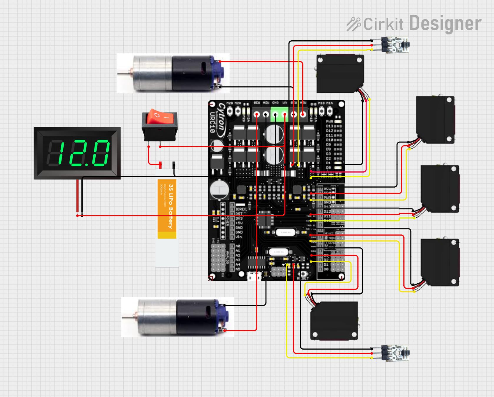
Circuit Documentation
Summary
This document provides a detailed overview of a circuit designed to control a robot using various sensors and motors. The circuit includes IR line sensors, diffuse IR sensors, DC motors, a LiPo battery, a rocker switch, a 7-segment panel voltmeter, and a Cytron URC10 motor driver shield. The microcontroller code is also provided to control the motors based on sensor inputs.
Component List
IR Line Sensor
- Pins: GND, VCC, SIGNAL
- Description: Used to detect lines on the ground for navigation.
FS-80NK Diffuse IR Sensor
- Pins: GND, VCC, SIGNAL
- Description: Used to detect obstacles and objects in the environment.
3S LiPo Battery
- Pins: -VE, +VE
- Description: Provides power to the entire circuit.
GM25 DC Motor
- Pins: +VE, -VE
- Description: Drives the robot's wheels.
Rocker Switch
- Pins: output, input
- Description: Used to turn the circuit on and off.
7-Segment Panel Voltmeter
- Pins: V+, V-
- Description: Displays the voltage of the battery.
URC10 Sumo Shield
- Pins: A5, VCC, GND, D2, D3, D8, D11, D12, A4, D10, D9
- Description: A shield for controlling motors and reading sensor inputs.
Cytron URC10
- Pins: M1A, M1B, VM, GND, M2A, M2B, G, V, D10, D11
- Description: Motor driver for controlling the DC motors.
Wiring Details
IR Line Sensor
- SIGNAL connected to A5 on URC10 Sumo Shield
- VCC connected to VCC on URC10 Sumo Shield
- GND connected to GND on URC10 Sumo Shield
FS-80NK Diffuse IR Sensor
- GND connected to GND on URC10 Sumo Shield
- VCC connected to VCC on URC10 Sumo Shield
- SIGNAL connected to:
- D2 on URC10 Sumo Shield
- D3 on URC10 Sumo Shield
- D8 on URC10 Sumo Shield
- D11 on URC10 Sumo Shield
- D12 on URC10 Sumo Shield
3S LiPo Battery
- -VE connected to V- on 7-Segment Panel Voltmeter and GND on Cytron URC10
- +VE connected to input on Rocker Switch
GM25 DC Motor
-VE connected to M1A on Cytron URC10
+VE connected to M1B on Cytron URC10
-VE connected to M2A on Cytron URC10
+VE connected to M2B on Cytron URC10
Rocker Switch
- output connected to V+ on 7-Segment Panel Voltmeter and VM on Cytron URC10
- input connected to +VE on 3S LiPo Battery
7-Segment Panel Voltmeter
- V+ connected to output on Rocker Switch
- V- connected to -VE on 3S LiPo Battery
URC10 Sumo Shield
- A5 connected to SIGNAL on IR Line Sensor
- VCC connected to VCC on IR Line Sensor
- GND connected to GND on IR Line Sensor
- D2 connected to SIGNAL on FS-80NK Diffuse IR Sensor
- D3 connected to SIGNAL on FS-80NK Diffuse IR Sensor
- D8 connected to SIGNAL on FS-80NK Diffuse IR Sensor
- D11 connected to SIGNAL on FS-80NK Diffuse IR Sensor
- D12 connected to SIGNAL on FS-80NK Diffuse IR Sensor
- A4 connected to SIGNAL on IR Line Sensor
- GND connected to GND on FS-80NK Diffuse IR Sensor
- VCC connected to VCC on FS-80NK Diffuse IR Sensor
Cytron URC10
- M1A connected to -VE on GM25 DC Motor
- M1B connected to +VE on GM25 DC Motor
- M2A connected to -VE on GM25 DC Motor
- M2B connected to +VE on GM25 DC Motor
- VM connected to output on Rocker Switch
- GND connected to -VE on 3S LiPo Battery
Documented Code
// Almost same as URC10 Motor Driver Pins
#define leftPWM 5
#define leftDir 4
#define rightPWM 6
#define rightDir 7

// Receiver pins
#define RX_CH_1 11   // Steering Channel (Turn Left / Right)
#define RX_CH_2 10  // Throttle channel (Move Forward / Backward)

// Parameters
#define deadZone 50  // Anything between -20 and 20 is STOP

int throttleCH, steeringCH;
int leftMotorSpeed, rightMotorSpeed;

void setup() {
  Serial.begin(9600);
  pinMode(leftPWM, OUTPUT);
  pinMode(leftDir, OUTPUT);
  pinMode(rightPWM, OUTPUT);
  pinMode(rightDir, OUTPUT);
  pinMode(RX_CH_1, INPUT);
  pinMode(RX_CH_2, INPUT);

  digitalWrite(leftDir, LOW);
  analogWrite(leftPWM, 0);
  digitalWrite(rightDir, LOW);
  analogWrite(rightPWM, 0);
}

// Main Loop
void loop() {

  // Read pulse width from receiver
  throttleCH = pulseIn(RX_CH_2, HIGH, 30000);
  steeringCH = pulseIn(RX_CH_1, HIGH, 30000);
  // Serial.print(" steeringCH : ");
  // Serial.println(steeringCH);
  // Serial.print(" throttleCH: ");
  // Serial.println(steeringCH);

  // Convert to PWM value (-255 to 255)
  throttleCH = pulseToPWM(throttleCH);
  steeringCH = pulseToPWM(steeringCH);

  // Channel 1 and Channel 2 Mixing
  leftMotorSpeed = throttleCH - steeringCH;
  rightMotorSpeed = throttleCH + steeringCH;

  // Drive motor
  drive(leftMotorSpeed, rightMotorSpeed);
  //  Serial.print("  leftMotorSpeed : ");
  //  Serial.println(leftMotorSpeed);
  //  Serial.print("   rightMotorSpeed: ");
  //  Serial.println(rightMotorSpeed);

  delay(1);
}

// Positive for forward, negative for reverse
void drive(int leftVal, int rightVal) {

  // Limit speed between -255 and 255
  leftVal = constrain(leftVal, -255, 255);
  rightVal = constrain(rightVal, -255, 255);

  // Set direction for left motor
  if (leftVal == 0) {
    analogWrite(leftDir, 0);
    analogWrite(leftPWM, 0);
  } else if (leftVal > 0) {
    digitalWrite(leftDir, HIGH);
    analogWrite(leftPWM, abs(leftVal));
  } else {
    digitalWrite(leftDir, LOW);
    analogWrite(leftPWM, abs(leftVal));

  }

  // Set direction for right motor
  if (rightVal == 0) {
    analogWrite(rightDir, 0);
    analogWrite(rightPWM, 0);

  } else if (rightVal > 0) {
    digitalWrite(rightDir, HIGH);
    analogWrite(rightPWM, abs(rightVal));
  } else {
    digitalWrite(rightDir, LOW);
    analogWrite(rightPWM, abs(rightVal));

  }
}

// Convert RC pulse value to motor PWM value
int pulseToPWM(int pulse) {

  // If we're receiving numbers, convert them to motor PWM
  if (pulse > 500) {
    pulse = map(pulse, 1000, 2000, -500, 500);
    pulse = constrain(pulse, -255, 255);
  } else {
    pulse = 0;
  }

  // Anything in deadzone should stop the motor
  if (abs(pulse) <= deadZone) {
    pulse = 0;
  }
  return pulse;
}
This concludes the documentation for the circuit.