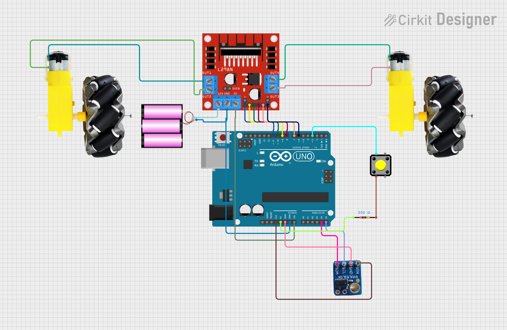
Arduino UNO Controlled Robot with PID Speed Regulation and VL53L0X Distance Sensing

Circuit Documentation
Summary
This circuit is designed to control a pair of DC motors using an Arduino UNO microcontroller in conjunction with an L298N DC motor driver. The Arduino UNO is also interfaced with a VL53L0X time-of-flight distance sensor to measure distances. The speed of the motors is regulated through a PID (Proportional-Integral-Derivative) control algorithm implemented in the Arduino's firmware, which uses distance measurements as feedback to adjust the motor speeds. A 12V battery is used to power the motor driver, which in turn powers the motors.
Component List
Arduino UNO
- Microcontroller board based on the ATmega328P.
- Controls the motors and interfaces with the VL53L0X sensor.
- Provides PWM outputs to the motor driver for speed control.
VL53L0X
- A time-of-flight distance sensor.
- Supplies distance measurements to the Arduino for motor speed control.
L298N DC Motor Driver
- A dual H-Bridge motor driver.
- Drives two DC motors using control signals from the Arduino UNO.
- Powered by a 12V battery.
Battery 12V
- Supplies power to the L298N motor driver and the motors.
Motor and Wheels (2 instances)
- DC motors with attached wheels.
- Driven by the L298N motor driver to move the vehicle.
Pushbutton
- A button used to start the motion control process.
Resistor
- A 200 Ohm resistor, likely used for pull-up or pull-down on the pushbutton.
Wiring Details
Arduino UNO
- A4 connected to VL53L0X SCL.
- A5 connected to VL53L0X SDA.
- D11 connected to L298N ENA.
- D9 connected to L298N IN1.
- D10 connected to L298N IN2.
- D8 connected to L298N IN3.
- D7 connected to L298N IN4.
- D6 connected to L298N ENB.
- GND connected to Battery - and L298N GND.
- Vin connected to L298N 5V.
- 3.3V connected to VL53L0X VIN.
- 5V connected to one side of the Resistor.
VL53L0X
- SCL connected to Arduino UNO A4.
- SDA connected to Arduino UNO A5.
- VIN connected to Arduino UNO 3.3V.
- GND connected to Arduino UNO GND.
L298N DC Motor Driver
- OUT1 connected to one Motor and Wheels VCC.
- OUT2 connected to one Motor and Wheels GND.
- OUT3 connected to the other Motor and Wheels GND.
- OUT4 connected to the other Motor and Wheels VCC.
- 12V connected to Battery +.
- GND connected to Arduino UNO GND and Battery -.
- 5V connected to Arduino UNO Vin.
- ENA, IN1, IN2, IN3, IN4, ENB controlled by Arduino UNO.
Battery 12V
- connected to L298N 12V.
- connected to Arduino UNO GND and L298N GND.
Motor and Wheels
- Two instances, each connected to L298N OUT1/OUT2 and OUT3/OUT4 respectively.
Pushbutton
- Pin 1 connected to Arduino UNO D3.
- Pin 2 connected to one side of the Resistor.
Resistor
- One side connected to Arduino UNO 5V.
- The other side connected to Pushbutton Pin 2.
Documented Code
#include <Wire.h>
#include <VL53L0X.h>

// Define pin assignments
int button = 3;
int motorpin1_1 = 9;
int motorpin1_2 = 10;
int enablemotor1 = 11;
int motorpin2_1 = 8;
int motorpin2_2 = 7;
int enablemotor2 = 6;

// Initialize variables for PID control
int timebefore = 0;
int setspeed = 200;
int motorspeed = 0;
int last_error = 0;
int Kp = 283, Kd = 500, Ki = 0.2;

// Create an instance of the VL53L0X sensor
VL53L0X sensor;

// Function prototypes
int PID_control();

void setup() {
    Serial.begin(9600);
    Wire.begin();
    if (!sensor.init()) {
        Serial.println("Failed to detect and initialize sensor!");
        while (1);
    }
    sensor.setTimeout(500);
    sensor.startContinuous();

    // Set motor control pins as outputs
    pinMode(motorpin1_1, OUTPUT);
    pinMode(motorpin1_2, OUTPUT);
    pinMode(enablemotor1, OUTPUT);
    pinMode(motorpin2_1, OUTPUT);
    pinMode(motorpin2_2, OUTPUT);
    pinMode(enablemotor2, OUTPUT);
    pinMode(button, INPUT);
}

void loop() {
    int currentstate = digitalRead(button);
    if (currentstate == 1 && last_button_state == 0) {
        int timeconsumed = (millis() - timebefore);
        uint16_t distance = sensor.readRangeContinuousMillimeters();
        int distance_cm = distance / 10;

        if (timeconsumed > 0) {
            motorspeed = (distance / 1000.0) / (timeconsumed / 1000.0);
            Serial.print("Motor Speed: ");
            Serial.println(motorspeed);
        }

        if (sensor.timeoutOccurred()) {
            Serial.println("Timeout!");
        } else {
            Serial.print("Distance: ");
            Serial.print(distance);
            Serial.println("mm");
            delay(100);
        }

        if (distance_cm < 10) {
            digitalWrite(enablemotor1, LOW);
            digitalWrite(enablemotor2, LOW);
        } else {
            PID_control();
        }
    }
    last_button_state = currentstate;
    delay(10);
}

int PID_control() {
    unsigned long currenttime = millis();
    int error = setspeed - motorspeed;
    unsigned long delta_time = (currenttime - timebefore) / 1000;
    int integral = error * delta_time;
    int derivative = (error - last_error) / delta_time;
    last_error = error;
    timebefore = currenttime;
    long int PID_output = Kp * error + Ki * integral + Kd * derivative;
    PID_output = constrain(PID_output, 0, 255);
    analogWrite(enablemotor1, PID_output);
    analogWrite(enablemotor2, PID_output);
    return PID_output;
}
This code is responsible for reading the distance from the VL53L0X sensor and controlling the speed of the motors using a PID control loop. The motors are driven by the L298N motor driver, which receives PWM signals from the Arduino UNO. The button is used to start the motion control process, and the PID algorithm adjusts the motor speed based on the distance measurements to maintain a set speed.